3Com 3C13886 Installation Guide - Page 34
3Com 3C13886 - Router OC-3 ATM SML Flexible Interface Card Manual
 |
UPC - 662705478456
View all 3Com 3C13886 manuals
Add to My Manuals
Save this manual to your list of manuals |
Page 34 highlights
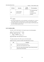
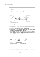
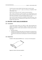
3Com Router Module Guide Chapter 2 Smart Interface Cards Caution: The wire marked TX in the E1 cable should be connected to the peer wire marked RX and the wire marked RX should be connected to the peer wire marked TX. DB -15 BNC Router BNC Network devices such as DDN Coaxial connector 75-ohm E1 trunk cable 75-ohm non-balanced coaxial cable Figure 2-18 Extending an E1 75-ohm non-balanced coaxial cable If the remote device has 120-ohm interface, it is needed to use a 75-ohm-to-120-ohm adapter or use a 120-ohm cable. 2) When the E1 cable is a 120-ohm balanced twisted pair cable: z Directly connect the RJ-45 connector of the cable to the RJ-45 port of the remote equipment, if there is no need to extend the E1 cable, or z Connect the RJ-45 connector of the cable to the network connector and the other end of the network connector to the network equipment through a 120-ohm E1 trunk cable, if cable extension is needed. DB-15 Router RJ-45 RJ-45 Network devices such as DDN Network interface connector 120-ohm balanced twisted pair 120-ohm E1 trunk cable Figure 2-19 Extending an E1 120-ohm balanced twisted pair cable Step 4: Power on the Router, and check the LEDs of the corresponding slot on the front panel: ON means that the SIC is operating normally and OFF means that the 2-19
-
 1
1 -
2
-
3
-
4
-
5
-
6
-
7
-
8
-
9
-
10
-
11
-
12
-
13
-
14
-
15
-
16
-
17
-
18
-
19
-
20
-
21
-
22
-
23
-
24
-
25
-
26
-
27
-
28
-
 29
29 -
 30
30 -
 31
31 -
 32
32 -
 33
33 -
 34
34 -
 35
35 -
 36
36 -
 37
37 -
 38
38 -
 39
39 -
40
-
41
-
42
-
43
-
44
-
45
-
46
-
47
-
48
-
49
-
50
-
51
-
52
-
53
-
54
-
55
-
56
-
57
-
58
-
59
-
60
-
61
-
62
-
63
-
64
-
65
-
66
-
67
-
68
-
69
-
70
-
71
-
72
-
73
-
74
-
75
-
76
-
77
-
78
-
79
-
80
-
81
-
82
-
83
-
84
-
85
-
86
-
87
-
88
-
89
-
90
-
91
-
92
-
93
-
94
-
95
-
96
-
97
-
98
-
99
-
100
-
101
-
102
-
103
-
104
-
105
-
106
-
107
-
108
-
109
-
110
-
111
-
112
-
113
-
114
-
115
-
116
-
117
-
118
-
119
-
120
-
121
-
122
-
123
-
124
-
125
-
126
-
127
-
128
-
129
-
130
-
131
-
132
-
133
-
134
-
135
-
136
-
137
-
138
-
139
-
140
-
141
-
142
-
143
-
144
-
145
-
146
-
147
-
148
-
149
-
150
-
151
-
152
-
153
-
154
-
155
-
156
-
157
-
158
-
159
-
160
-
161
-
162
-
163
-
164
-
165
-
166
-
167
-
168
-
169
-
170
-
171
 |
 |
