3Ware 7506-8 User Guide - Page 26
Installing a Parallel ATA RAID Controller - pci x
 |
UPC - 693494750683
View all 3Ware 7506-8 manuals
Add to My Manuals
Save this manual to your list of manuals |
Page 26 highlights
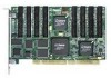
3ware Hardware Installation 6 Gently remove the ATA RAID Controller from the PCI slot. 7 Remove the cables from the ATA RAID Controller and discard. Reusing interface cables is not recommended. Installing a Parallel ATA RAID Controller Note: If you are not installing a Parallel ATA RAID Controller, continue to page 21 "Installing a Serial ATA RAID Controller". JP2 LED drive status connector Note: Pin 1 and 4 are 3.3V and pin 2 and 3 are ground Plug cable to either pins 1 and 2 or pins 3 and 4. Ports: 65 4 7 3 21 0 0 Serial Number (on plate) Figure 5. 8-Port Escalade 750x-8 ATA RAID Controller Layout Note: The LED drive status connector, if used, will flash for any I/ O activity on any port. Connect the interface cables to the Escalade ATA RAID Controller 1 Connect the interface cables supplied with the product to the ATA RAID Controller. See Figure 5. 18 3ware Escalade ATA RAID Controller User Guide
-
 1
1 -
2
-
3
-
4
-
5
-
6
-
7
-
8
-
9
-
10
-
11
-
12
-
13
-
14
-
15
-
16
-
17
-
18
-
19
-
20
-
 21
21 -
 22
22 -
 23
23 -
 24
24 -
 25
25 -
 26
26 -
 27
27 -
 28
28 -
 29
29 -
 30
30 -
 31
31 -
32
-
33
-
34
-
35
-
36
-
37
-
38
-
39
-
40
-
41
-
42
-
43
-
44
-
45
-
46
-
47
-
48
-
49
-
50
-
51
-
52
-
53
-
54
-
55
-
56
-
57
-
58
-
59
-
60
-
61
-
62
-
63
-
64
-
65
-
66
-
67
-
68
-
69
-
70
-
71
-
72
-
73
-
74
-
75
-
76
-
77
-
78
-
79
-
80
-
81
-
82
-
83
-
84
-
85
-
86
-
87
-
88
-
89
-
90
-
91
-
92
-
93
-
94
-
95
-
96
-
97
-
98
-
99
-
100
-
101
-
102
-
103
-
104
-
105
-
106
-
107
-
108
-
109
-
110
-
111
-
112
-
113
-
114
-
115
-
116
-
117
-
118
-
119
-
120
-
121
-
122
-
123
-
124
-
125
-
126
 |
 |