3Ware 7506-8 User Guide - Page 28
Connect the drives to the interface cables, Single, Master
 |
UPC - 693494750683
View all 3Ware 7506-8 manuals
Add to My Manuals
Save this manual to your list of manuals |
Page 28 highlights
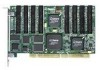
3ware Hardware Installation troller inside the chassis. The short 4-port or 8-port Escalade ATA RAID Controller is keyed to ensure proper installation in a full-sized PCI slot. 6 Ensure that the contacts will mate with the grooves in the slot. Press down gently on the edge of the ATA RAID Controller directly above the slot until it is fully seated. 7 Check that the ATA RAID Controller's metal bracket covers the hole in the case and secure the bracket with the screw that was used to secure the filler bracket in step 4. Connect the drives to the interface cables 1 Be sure to use the supplied cables. With the higher speeds of UltraATA133 and UltraATA-100, using quality cables is important. 2 Before connecting your drives, check your drives' jumper setting. The range of settings provided vary by manufacturer as do the method for adjusting them. Refer to information provided with your drives for the method required to set them. To operate properly, the Escalade Parallel ATA RAID Controller requires that drives be set as Single (if available on your drive) or Master. 3 If your drives are not already installed in the computer chassis, do so now. Be sure that the drives are connected to the power supply. 4 For each drive, select the black end of an interface cable not connected to the ATA RAID Controller and plug it into the drive or drive carrier. The cable's colored edge denotes Pin 1 and should be adjacent to the 4-pin power plug. Note: Continue to page 26 "Check your installation and close the case". 20 3ware Escalade ATA RAID Controller User Guide
-
 1
1 -
2
-
3
-
4
-
5
-
6
-
7
-
8
-
9
-
10
-
11
-
12
-
13
-
14
-
15
-
16
-
17
-
18
-
19
-
20
-
21
-
22
-
 23
23 -
 24
24 -
 25
25 -
 26
26 -
 27
27 -
 28
28 -
 29
29 -
 30
30 -
 31
31 -
 32
32 -
 33
33 -
34
-
35
-
36
-
37
-
38
-
39
-
40
-
41
-
42
-
43
-
44
-
45
-
46
-
47
-
48
-
49
-
50
-
51
-
52
-
53
-
54
-
55
-
56
-
57
-
58
-
59
-
60
-
61
-
62
-
63
-
64
-
65
-
66
-
67
-
68
-
69
-
70
-
71
-
72
-
73
-
74
-
75
-
76
-
77
-
78
-
79
-
80
-
81
-
82
-
83
-
84
-
85
-
86
-
87
-
88
-
89
-
90
-
91
-
92
-
93
-
94
-
95
-
96
-
97
-
98
-
99
-
100
-
101
-
102
-
103
-
104
-
105
-
106
-
107
-
108
-
109
-
110
-
111
-
112
-
113
-
114
-
115
-
116
-
117
-
118
-
119
-
120
-
121
-
122
-
123
-
124
-
125
-
126
 |
 |