Adaptec 412R User Guide - Page 10
Overview, DuraStor 412R
 |
UPC - 760884139691
View all Adaptec 412R manuals
Add to My Manuals
Save this manual to your list of manuals |
Page 10 highlights
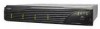
DuraStor 412R/6320SS/7320SS Installation and User's Guide Overview DuraStor 412R Figure 1-1 shows the components of the DuraStor 412R drive enclosure. Drive Status LEDs (left column of LEDs) Drive Activity LEDs (right column of LEDs) Power On LED Channel Status LED Power Supply Status LED Fan Status LED Alarm Reset Button 350-watt hot-pluggable independent power supplies Dual in-line 80-CFM hot swappable cooling fans SAFTE Disk I/O Card SAF-TE Service & VT-100 Ports Single-Bus Module (Optional) Figure 1-1 DuraStor 412R Drive Enclosure Cover Plate 1-2
-
 1
1 -
2
-
3
-
4
-
 5
5 -
 6
6 -
 7
7 -
 8
8 -
 9
9 -
 10
10 -
 11
11 -
 12
12 -
 13
13 -
 14
14 -
 15
15 -
16
-
17
-
18
-
19
-
20
-
21
-
22
-
23
-
24
-
25
-
26
-
27
-
28
-
29
-
30
-
31
-
32
-
33
-
34
-
35
-
36
-
37
-
38
-
39
-
40
-
41
-
42
-
43
-
44
-
45
-
46
-
47
-
48
-
49
-
50
-
51
-
52
-
53
-
54
-
55
-
56
-
57
-
58
-
59
-
60
-
61
-
62
-
63
-
64
-
65
-
66
-
67
-
68
-
69
-
70
-
71
-
72
-
73
-
74
-
75
-
76
-
77
-
78
-
79
-
80
-
81
-
82
-
83
-
84
-
85
-
86
-
87
-
88
-
89
-
90
-
91
-
92
-
93
-
94
-
95
-
96
-
97
-
98
-
99
-
100
-
101
-
102
-
103
-
104
-
105
-
106
-
107
-
108
-
109
-
110
-
111
-
112
-
113
-
114
-
115
-
116
-
117
-
118
-
119
-
120
-
121
-
122
-
123
-
124
-
125
-
126
-
127
-
128
-
129
-
130
-
131
-
132
-
133
-
134
-
135
-
136
-
137
-
138
-
139
-
140
-
141
-
142
-
143
-
144
-
145
-
146
-
147
-
148
-
149
-
150
-
151
-
152
-
153
-
154
-
155
-
156
-
157
-
158
-
159
-
160
-
161
-
162
-
163
-
164
-
165
-
166
-
167
-
168
-
169
-
170
-
171
-
172
-
173
-
174
-
175
-
176
-
177
-
178
-
179
-
180
-
181
-
182
-
183
-
184
-
185
-
186
-
187
-
188
-
189
-
190
-
191
-
192
-
193
-
194
-
195
-
196
-
197
-
198
-
199
-
200
-
201
-
202
-
203
-
204
-
205
-
206
-
207
-
208
-
209
-
210
 |
 |

1-2
DuraStor 412R/6320SS/7320SS Installation and User’s Guide
Overview
DuraStor 412R
Figure 1-1
shows the components of the DuraStor 412R drive
enclosure.
Figure 1-1
DuraStor 412R Drive Enclosure
Cover Plate
Single-Bus
Module (Optional)
350-watt hot-pluggable
independent power supplies
Dual in-line 80-CFM hot
swappable cooling fans
SAFTE Disk I/O Card
SAF-TE Service & VT-100 Ports
Drive St
atus LEDs
(left
column o
f LEDs)
D
rive Acti
vity LEDs
(right c
olumn of
LEDs)
Power
On LED
Cha
nnel Stat
us LED
Power Sup
ply Statu
s LED
Fan
Status LE
D
Alarm Re
set Butto
n