Adaptec 412R User Guide - Page 73
Cooling Fan Module
 |
UPC - 760884139691
View all Adaptec 412R manuals
Add to My Manuals
Save this manual to your list of manuals |
Page 73 highlights
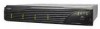
Understanding and Maintaining Components 4 Remove the replacement PSU from the shipping container. Inspect the PSU for obvious damage. 5 Slide the new PSU into the open bay until it seats completely and the retaining latch resets. 6 Reconnect the power cord and replace the security bale. 7 Turn ON the PSU. The PSU's Power On LED lights up, its Fault LED goes out, and the Power Supply LED on the front bezel changes to solid green to indicate normal PSU status. Cooling Fan Module The cooling system consists of two high-performance (80-CFM) cooling fans enclosed in a single fan module (see Figure 5-12). The fan module fits into the open bay at the rear of the storage subsystem and is hot-swappable. Figure 5-12 Cooling Fan Module If the storage subsystem temperature exceeds the established threshold of 60° C (140° F), the fan status LED on the front bezel begins to flash amber. (The SAF-TE processor monitors the temperature and reports when this condition occurs.) 5-15
-
 1
1 -
2
-
3
-
4
-
5
-
6
-
7
-
8
-
9
-
10
-
11
-
12
-
13
-
14
-
15
-
16
-
17
-
18
-
19
-
20
-
21
-
22
-
23
-
24
-
25
-
26
-
27
-
28
-
29
-
30
-
31
-
32
-
33
-
34
-
35
-
36
-
37
-
38
-
39
-
40
-
41
-
42
-
43
-
44
-
45
-
46
-
47
-
48
-
49
-
50
-
51
-
52
-
53
-
54
-
55
-
56
-
57
-
58
-
59
-
60
-
61
-
62
-
63
-
64
-
65
-
66
-
67
-
 68
68 -
 69
69 -
 70
70 -
 71
71 -
 72
72 -
 73
73 -
 74
74 -
 75
75 -
 76
76 -
 77
77 -
 78
78 -
79
-
80
-
81
-
82
-
83
-
84
-
85
-
86
-
87
-
88
-
89
-
90
-
91
-
92
-
93
-
94
-
95
-
96
-
97
-
98
-
99
-
100
-
101
-
102
-
103
-
104
-
105
-
106
-
107
-
108
-
109
-
110
-
111
-
112
-
113
-
114
-
115
-
116
-
117
-
118
-
119
-
120
-
121
-
122
-
123
-
124
-
125
-
126
-
127
-
128
-
129
-
130
-
131
-
132
-
133
-
134
-
135
-
136
-
137
-
138
-
139
-
140
-
141
-
142
-
143
-
144
-
145
-
146
-
147
-
148
-
149
-
150
-
151
-
152
-
153
-
154
-
155
-
156
-
157
-
158
-
159
-
160
-
161
-
162
-
163
-
164
-
165
-
166
-
167
-
168
-
169
-
170
-
171
-
172
-
173
-
174
-
175
-
176
-
177
-
178
-
179
-
180
-
181
-
182
-
183
-
184
-
185
-
186
-
187
-
188
-
189
-
190
-
191
-
192
-
193
-
194
-
195
-
196
-
197
-
198
-
199
-
200
-
201
-
202
-
203
-
204
-
205
-
206
-
207
-
208
-
209
-
210
 |
 |
