Adaptec 412R User Guide - Page 71
Power Supply Units
 |
UPC - 760884139691
View all Adaptec 412R manuals
Add to My Manuals
Save this manual to your list of manuals |
Page 71 highlights
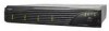
Understanding and Maintaining Components Power Supply Units The DuraStor power system consists of two 350-watt hotswappable power supply units (PSUs), each with independent AC power and cooling fans. This system provides the storage subsystem with N+1 redundant power. Each PSU has autoswitching circuitry for use with either 110V or 220V AC systems. A PSU is shown in Figure 5-10. LEDs Power switch Power cord connector and security bale Figure 5-10 Power Supply Unit (PSU) Each PSU has a power switch and a Power On LED, a power cord connector (with a security bale that fits over the power cord to prevent accidental disconnections), and an independent AC power cord. (The power switches are identified with a 1 for ON and a 0 for OFF. When you turn on a PSU, its own Power-on LED and the Power Supply LED on the front bezel light up, and the storage subsystem performs a power-on self-test (POST). If a PSU fails, the Power Supply LED changes from solid green to solid amber and the audible alarm sounds. On the failed PSU, the green Power On LED goes out and the amber Fault LED lights up. If only one power supply is operational, the front bezel Power LED is amber. 5-13
-
 1
1 -
2
-
3
-
4
-
5
-
6
-
7
-
8
-
9
-
10
-
11
-
12
-
13
-
14
-
15
-
16
-
17
-
18
-
19
-
20
-
21
-
22
-
23
-
24
-
25
-
26
-
27
-
28
-
29
-
30
-
31
-
32
-
33
-
34
-
35
-
36
-
37
-
38
-
39
-
40
-
41
-
42
-
43
-
44
-
45
-
46
-
47
-
48
-
49
-
50
-
51
-
52
-
53
-
54
-
55
-
56
-
57
-
58
-
59
-
60
-
61
-
62
-
63
-
64
-
65
-
 66
66 -
 67
67 -
 68
68 -
 69
69 -
 70
70 -
 71
71 -
 72
72 -
 73
73 -
 74
74 -
 75
75 -
 76
76 -
77
-
78
-
79
-
80
-
81
-
82
-
83
-
84
-
85
-
86
-
87
-
88
-
89
-
90
-
91
-
92
-
93
-
94
-
95
-
96
-
97
-
98
-
99
-
100
-
101
-
102
-
103
-
104
-
105
-
106
-
107
-
108
-
109
-
110
-
111
-
112
-
113
-
114
-
115
-
116
-
117
-
118
-
119
-
120
-
121
-
122
-
123
-
124
-
125
-
126
-
127
-
128
-
129
-
130
-
131
-
132
-
133
-
134
-
135
-
136
-
137
-
138
-
139
-
140
-
141
-
142
-
143
-
144
-
145
-
146
-
147
-
148
-
149
-
150
-
151
-
152
-
153
-
154
-
155
-
156
-
157
-
158
-
159
-
160
-
161
-
162
-
163
-
164
-
165
-
166
-
167
-
168
-
169
-
170
-
171
-
172
-
173
-
174
-
175
-
176
-
177
-
178
-
179
-
180
-
181
-
182
-
183
-
184
-
185
-
186
-
187
-
188
-
189
-
190
-
191
-
192
-
193
-
194
-
195
-
196
-
197
-
198
-
199
-
200
-
201
-
202
-
203
-
204
-
205
-
206
-
207
-
208
-
209
-
210
 |
 |
