Brother International BAS-375E Instruction Manual - English - Page 25
OPERATING PROCEDURE, 1. Part names and functions of the operation panel
 |
View all Brother International BAS-375E manuals
Add to My Manuals
Save this manual to your list of manuals |
Page 25 highlights
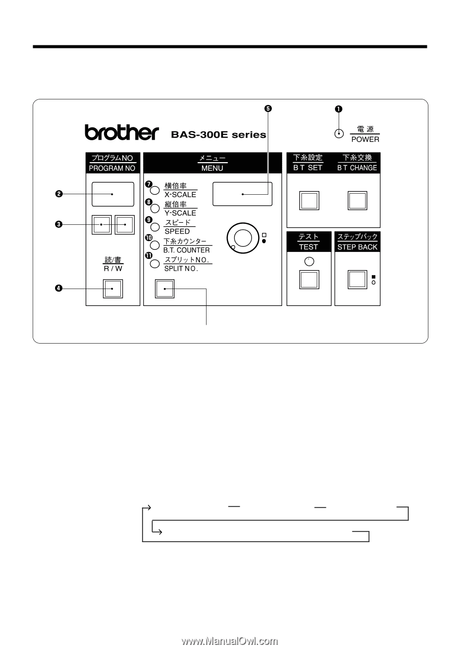
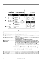
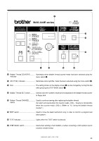
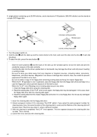
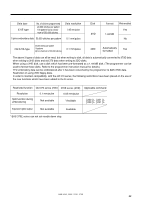
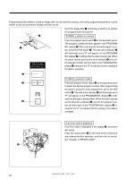
Chapter 5 OPERATING PROCEDURE Chapter 5 OPERATING PROCEDURE 1. Part names and functions of the operation panel y q POWER indicator When the power is turned on, the indicator lights to show that the power is on. w PROGRAM No. display Displays the program number 00 - 99. e Program select switch Used to select the program number when reading a program from or writing a program to disk. r Program Read/Write switch ........ Used to read a program from floppy disk, or to write a newly programmed stitch pattern to floppy disk. Up to ten patterns (00 - 99) can be stored on each disk. t Display screen Used to display data such as menus, errors and memory switch settings. y Menu switch Used to select the desired menu (scale, speed, bobbin thread counter, split No.). One of the indicators u - !1 illuminates to indicate the menu selected, and the setting for that menu them appears on the display screen t. The illuminated indicator changes in the following order each time the switch is pressed. X-SCALE indicator u Y-SCALE indicator i SPEED indicator o B.T. COUNTER indicator !0 SPLIT NO. indicator !1 u X-SCALE indicator Illuminates when X-scale mode has been selected using the menu switch y. i Y-SCALE indicator Illuminates when Y-scale mode has been selected using the menu switch y. o SPEED indicator Illuminates when speed mode has been selected using the menu switch y. BAS-364E, 366E, 370E, 375E 19
-
 1
1 -
2
-
3
-
4
-
5
-
6
-
7
-
8
-
9
-
10
-
11
-
12
-
13
-
14
-
15
-
16
-
17
-
18
-
19
-
 20
20 -
 21
21 -
 22
22 -
 23
23 -
 24
24 -
 25
25 -
 26
26 -
 27
27 -
 28
28 -
 29
29 -
 30
30 -
31
-
32
-
33
-
34
-
35
-
36
-
37
-
38
-
39
-
40
-
41
-
42
-
43
-
44
-
45
-
46
-
47
-
48
-
49
-
50
-
51
-
52
-
53
-
54
-
55
-
56
-
57
-
58
-
59
-
60
-
61
-
62
-
63
-
64
-
65
-
66
-
67
-
68
 |
 |