Brother International BAS-375E Instruction Manual - English - Page 6

Contents

Page 6 highlights

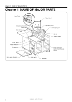
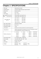
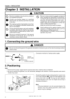
Contents Chapter 1 NAME OF MAJOR PARTS .... 1 Chapter 2 SPECIFICATIONS 2 Chapter 3 INSTALLATION 3 1. Connecting the ground wire 3 2. Positioning 3 3. Installing the needle plates 4 4. Installing the work clamp hinge 5 5. Installing the arm motor cover 5 6. Installing the foot switch 6 7. Installing the programmer box 6 8. Installing the programmer 6 9. Installing the spool stand 7 10. Preparation of cassette 7 11. Lubrication 8 12. Draining oil 9 13. Applying grease 10 14. Adjusting the air pressure 11 Chapter 4 CORRECT OPERATION ... 12 1. Turning the pulley by hand 12 2. Installing the needle 12 3. Threading the upper thread 13 4. Winding the lower thread 14 5. Installing the bobbin case 15 6. Thread tension 16 7. Work clamp 17 8. Selecting Intermittent feed or continuous feed ...... 18 Chapter 5 OPERATING PROCEDURE... 19 1. Part names and functions of the operation panel .. 19 2. Using the floppy disk 21 3. Using the program R/W (Read/Write) switch ........ 23 4. Using the emergency stop switch 24 5. Adjusting the sewing speed control 25 6. Changing the X-scale and Y-scale settings..... 25 7. Using the TEST switch (Checking the sewing pattern 26 8. Using the STEP BACK switch 27 9. Using single split mode 28 10. Using the bobbin thread counter 29 11. Using production counter 30 12. Shifting a stitch pattern 31 Chapter 6 Sewing 32 1. Before starting sewing 32 2. Sewing operation 33 Chapter 7 STANDARD ADJUSTMENTS .... 34 1. Needle and rotary hook timing 34 2. Adjusting the needle bar height 35 3. Adjusting the needle clearance 35 4. Adjusting the presser foot 36 5. Changing the presser foot lift amount ...... 37 6. Replacing the fixed knife and movable knife ..... 38 7. Adjusting the inner rotary hook bobbin case holder position 39 8. Checking the input voltage 40 9. Clearing all memory settings 40 Chapter 8 DEVICES 41 1. Needle thread presser 41 2. Beam sensor-type needle thread breakage detecor 41 3. Two-stage thread tension mechanism ..... 42 4. Stepping foot control mechanism 42 5. Needle cooler 43 6. Installing the bottom plunger 43 7. Jig pattern sensor 44 8. Sub clamp (BAS-370E, 375E only 45 Chapter 9 CLEANING AND INSPECTION ... 47 1. Rotary hook 47 2. Eye guard 47 3. Checking the needle 48 Chapter 10 DIP SWITCH 49 1. Panel DIP switch functions 49 2. DIP switches inside the control box .......... 50 Chapter 11 CHANGING SPECIAL FUNCTIONS USING AND THE MEMORY SWITCHES ..... 52 Chapter 12 ERROR CODE 57 Chapter 13 TROUBLESHOOTING ... 59 OPERATION FLOW CHART 61

  • 1
  • 2
  • 3
  • 4
  • 5
  • 6
  • 7
  • 8
  • 9
  • 10
  • 11
  • 12
  • 13
  • 14
  • 15
  • 16
  • 17
  • 18
  • 19
  • 20
  • 21
  • 22
  • 23
  • 24
  • 25
  • 26
  • 27
  • 28
  • 29
  • 30
  • 31
  • 32
  • 33
  • 34
  • 35
  • 36
  • 37
  • 38
  • 39
  • 40
  • 41
  • 42
  • 43
  • 44
  • 45
  • 46
  • 47
  • 48
  • 49
  • 50
  • 51
  • 52
  • 53
  • 54
  • 55
  • 56
  • 57
  • 58
  • 59
  • 60
  • 61
  • 62
  • 63
  • 64
  • 65
  • 66
  • 67
  • 68

Chapter 1
NAME OF MAJOR PARTS
....
1
Chapter 2 SPECIFICATIONS
................
2
Chapter 3 INSTALLATION
........................
3
1. Connecting the ground wire
........................
3
2. Positioning
........................................................
3
3. Installing the needle plates
..........................
4
4. Installing the work clamp hinge
..................
5
5. Installing the arm motor cover
....................
5
6. Installing the foot switch
...............................
6
7. Installing the programmer box
....................
6
8. Installing the programmer
............................
6
9. Installing the spool stand
..............................
7
10. Preparation of cassette
..............................
7
11. Lubrication
.....................................................
8
12. Draining oil
.....................................................
9
13. Applying grease
............................................
10
14. Adjusting the air pressure
..........................
11
Chapter 4 CORRECT OPERATION
... 12
1. Turning the pulley by hand
..........................
12
2. Installing the needle
.......................................
12
3. Threading the upper thread
.........................
13
4. Winding the lower thread
.............................
14
5.
Installing the bobbin case
.................................
15
6. Thread tension
................................................
16
7. Work clamp
......................................................
17
8.
Selecting Intermittent feed or continuous feed
......
18
Chapter 5
OPERATING PROCEDURE
... 19
1.
Part names and functions of the operation panel
.. 19
2. Using the floppy disk
.....................................
21
3.
Using the program R/W (Read/Write) switch
........
23
4. Using the emergency stop switch
..............
24
5. Adjusting the sewing speed control
...........
25
6.
Changing the X-scale and Y-scale settings
.....
25
7. Using the TEST switch
(Checking the sewing pattern)
......................
26
8. Using the STEP BACK switch
....................
27
9. Using single split mode
.................................
28
10. Using the bobbin thread counter
.............
29
11.
Using production counter
..........................
30
12. Shifting a stitch pattern
...............................
31
Contents
Chapter 6 Sewing
........................................
32
1. Before starting sewing
....
..............................
32
2. Sewing operation
............................................
33
Chapter 7
STANDARD ADJUSTMENTS
....
34
1. Needle and rotary hook timing
...................
34
2. Adjusting the needle bar height
.................
35
3. Adjusting the needle clearance
..................
35
4. Adjusting the presser foot
............................
36
5. Changing the presser foot lift amount
......
37
6.
Replacing the fixed knife and movable knife
.....
38
7. Adjusting the inner rotary hook
bobbin case holder position
........................
39
8. Checking the input voltage
..........................
40
9. Clearing all memory settings
.......................
40
Chapter 8 DEVICES
...................................
41
1. Needle thread presser
..................................
41
2. Beam sensor-type needle thread
breakage detecor
..........................................
41
3. Two-stage thread tension mechanism
.....
42
4. Stepping foot control mechanism
..............
42
5. Needle cooler
..................................................
43
6. Installing the bottom plunger
.......................
43
7. Jig pattern sensor
...........................................
44
8. Sub clamp (BAS-370E, 375E only)
...........
45
Chapter 9
CLEANING
AND INSPECTION
... 47
1. Rotary hook
......................................................
47
2. Eye guard
.........................................................
47
3. Checking the needle
......................................
48
Chapter 10 DIP SWITCH
.........................
49
1. Panel DIP switch functions
..........................
49
2. DIP switches inside the control box
..........
50
Chapter 11
CHANGING SPECIAL FUNCTIONS
USING
AND THE MEMORY SWITCHES
.....
52
Chapter 12 ERROR CODE
.....................
57
Chapter 13 TROUBLESHOOTING
... 59
OPERATION FLOW CHART
.................
61