Brother International BAS-375E Instruction Manual - English - Page 43
Changing the presser foot lift amount
 |
View all Brother International BAS-375E manuals
Add to My Manuals
Save this manual to your list of manuals |
Page 43 highlights
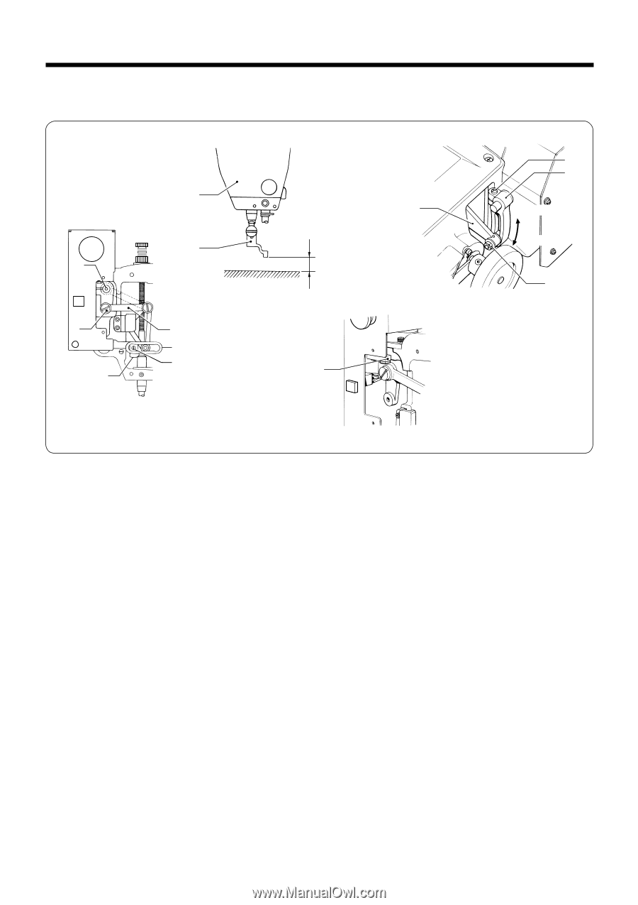
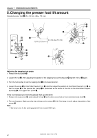
Chapter 7 STANDARD ADJUSTMENTS 5. Changing the presser foot lift amount Standard presser foot q lift is 3.2 mm. (Max. 7.2 mm) !2 !0 u q r !1 o i e 3.2 mm (max.7.2 mm) !3 y t Increase Decrease w Adjusting the stepping foot stroke 1. Remove the face plate w. 2. Loosen the nut e. After adjusting the position of the stepping foot connecting rod r, tighten the nut e again. 3. Turn the hand pulley to set the stepping foot q to its lowest position. 4. Loosen the screw y of intermittent feed arm (L) t, and then adjust the position of intermittent feed arm (L) t so that the screw i of the presser bar clamp u is positioned at the center of the slot on the intermittent support assembly o. Then tighten the screw y. If it is not necessary to move the presser foot up and down 1. Remove the stud screw !,0 and reattach link (L) !1 to the other screw hole of the intermittent feed shaft !.2 2. Turn on the power. Make sure that the red lamp on the sensor !3 is lit. If the lamp is not lit, adjust the position of the sensor !.3 Note If the lamp is not lit, the sewing speed will not exceed 2000 rpm. BAS-364E, 366E, 370E, 375E 37
-
 1
1 -
2
-
3
-
4
-
5
-
6
-
7
-
8
-
9
-
10
-
11
-
12
-
13
-
14
-
15
-
16
-
17
-
18
-
19
-
20
-
21
-
22
-
23
-
24
-
25
-
26
-
27
-
28
-
29
-
30
-
31
-
32
-
33
-
34
-
35
-
36
-
37
-
 38
38 -
 39
39 -
 40
40 -
 41
41 -
 42
42 -
 43
43 -
 44
44 -
 45
45 -
 46
46 -
 47
47 -
 48
48 -
49
-
50
-
51
-
52
-
53
-
54
-
55
-
56
-
57
-
58
-
59
-
60
-
61
-
62
-
63
-
64
-
65
-
66
-
67
-
68
 |
 |