Brother International HL 1240 Service Manual - Page 74
Main Cover
 |
UPC - 012502600855
View all Brother International HL 1240 manuals
Add to My Manuals
Save this manual to your list of manuals |
Page 74 highlights
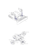
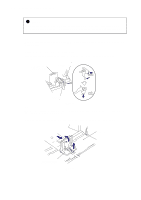
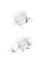
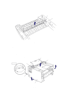
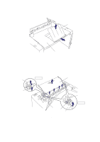
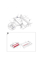
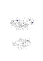
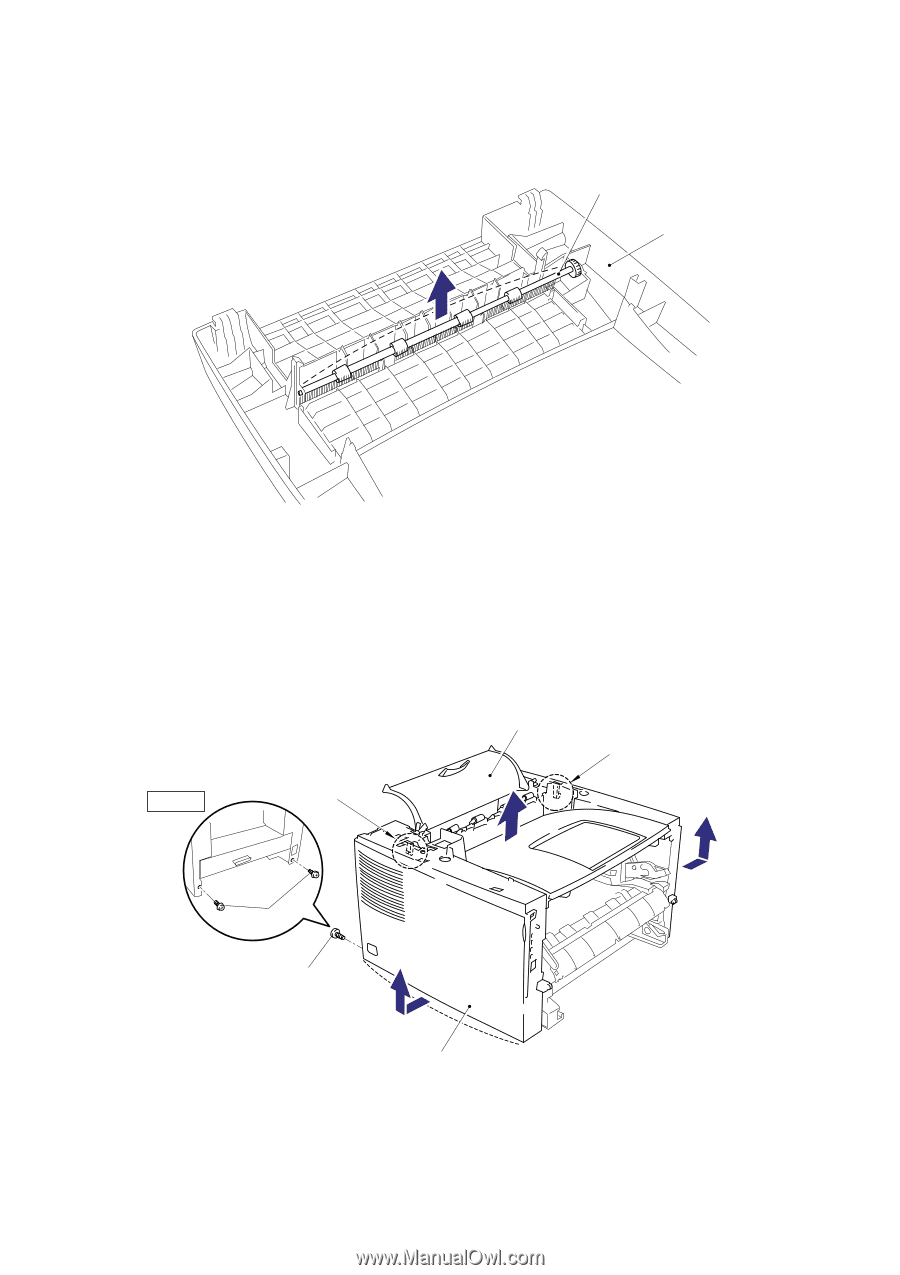
CHAPTER 4 DISASSEMBLY AND RE-ASSEMBLY (5) Turn the top cover upside down and remove the second eject roller ASSY by lifting the middle of the roller upwards until the roller releases from the cover. Second eject roller ASSY Top cover Fig. 4-18 3.6 Main Cover (1) Remove the two M3x8 Taptite screws from the rear of the main cover. (2) Release the hooks at the right and left hand top sides of the printer, then, while pulling the cover outwards to clear the power socket and switch, lift up the main cover to remove it complete with the rear cover. Taptite, bind M3x8 Rear cover (hook) Step (1) (hook) Taptite, bind M3x8 Main cover Fig. 4-19 4-12
-
 1
1 -
2
-
3
-
4
-
5
-
6
-
7
-
8
-
9
-
10
-
11
-
12
-
13
-
14
-
15
-
16
-
17
-
18
-
19
-
20
-
21
-
22
-
23
-
24
-
25
-
26
-
27
-
28
-
29
-
30
-
31
-
32
-
33
-
34
-
35
-
36
-
37
-
38
-
39
-
40
-
41
-
42
-
43
-
44
-
45
-
46
-
47
-
48
-
49
-
50
-
51
-
52
-
53
-
54
-
55
-
56
-
57
-
58
-
59
-
60
-
61
-
62
-
63
-
64
-
65
-
66
-
67
-
68
-
 69
69 -
 70
70 -
 71
71 -
 72
72 -
 73
73 -
 74
74 -
 75
75 -
 76
76 -
 77
77 -
 78
78 -
 79
79 -
80
-
81
-
82
-
83
-
84
-
85
-
86
-
87
-
88
-
89
-
90
-
91
-
92
-
93
-
94
-
95
-
96
-
97
-
98
-
99
-
100
-
101
-
102
-
103
-
104
-
105
-
106
-
107
-
108
-
109
-
110
-
111
-
112
-
113
-
114
-
115
-
116
-
117
-
118
-
119
-
120
-
121
-
122
-
123
-
124
-
125
-
126
-
127
-
128
-
129
-
130
-
131
-
132
-
133
-
134
-
135
-
136
-
137
-
138
-
139
-
140
-
141
-
142
-
143
-
144
-
145
-
146
-
147
-
148
-
149
-
150
-
151
-
152
-
153
-
154
-
155
-
156
-
157
-
158
-
159
-
160
-
161
-
162
-
163
-
164
-
165
-
166
-
167
-
168
-
169
-
170
-
171
-
172
-
173
-
174
-
175
-
176
-
177
-
178
-
179
-
180
-
181
-
182
-
183
-
184
-
185
-
186
-
187
-
188
-
189
-
190
-
191
-
192
-
193
-
194
-
195
-
196
-
197
-
198
-
199
-
200
-
201
-
202
-
203
-
204
-
205
-
206
-
207
-
208
-
209
-
210
-
211
-
212
-
213
-
214
-
215
-
216
-
217
-
218
-
219
-
220
-
221
-
222
-
223
-
224
-
225
-
226
-
227
-
228
-
229
-
230
-
231
-
232
-
233
-
234
-
235
-
236
-
237
-
238
-
239
-
240
-
241
-
242
-
243
-
244
-
245
-
246
-
247
-
248
-
249
-
250
-
251
-
252
-
253
-
254
-
255
-
256
-
257
-
258
-
259
-
260
-
261
-
262
-
263
-
264
-
265
-
266
-
267
-
268
-
269
-
270
-
271
-
272
-
273
-
274
-
275
-
276
-
277
-
278
-
279
-
280
-
281
-
282
-
283
-
284
-
285
-
286
-
287
-
288
-
289
-
290
-
291
-
292
-
293
-
294
-
295
-
296
-
297
-
298
-
299
-
300
-
301
-
302
-
303
-
304
-
305
-
306
-
307
-
308
-
309
-
310
-
311
-
312
-
313
-
314
-
315
-
316
-
317
-
318
-
319
-
320
-
321
-
322
-
323
-
324
-
325
-
326
-
327
-
328
-
329
-
330
-
331
-
332
-
333
 |
 |
CHAPTER 4
DISASSEMBLY AND RE-ASSEMBLY
4-12
(5)
Turn the top cover upside down and remove the second eject roller ASSY by lifting the
middle of the roller upwards until the roller releases from the cover.
Fig. 4-18
3.6
Main Cover
(1)
Remove the two M3x8 Taptite screws from the rear of the main cover.
(2)
Release the hooks at the right and left hand top sides of the printer, then, while pulling the
cover outwards to clear the power socket and switch, lift up the main cover to remove it
complete with the rear cover.
Fig. 4-19
Top cover
Second eject roller ASSY
Rear cover
Taptite, bind M3x8
(hook)
(hook)
Main cover
Step (1)
Taptite, bind M3x8