Brother International HL 1240 Service Manual - Page 97
Fan Motor ASSY
 |
UPC - 012502600855
View all Brother International HL 1240 manuals
Add to My Manuals
Save this manual to your list of manuals |
Page 97 highlights
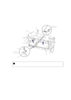
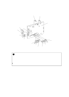
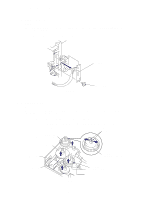
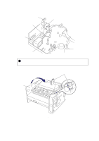
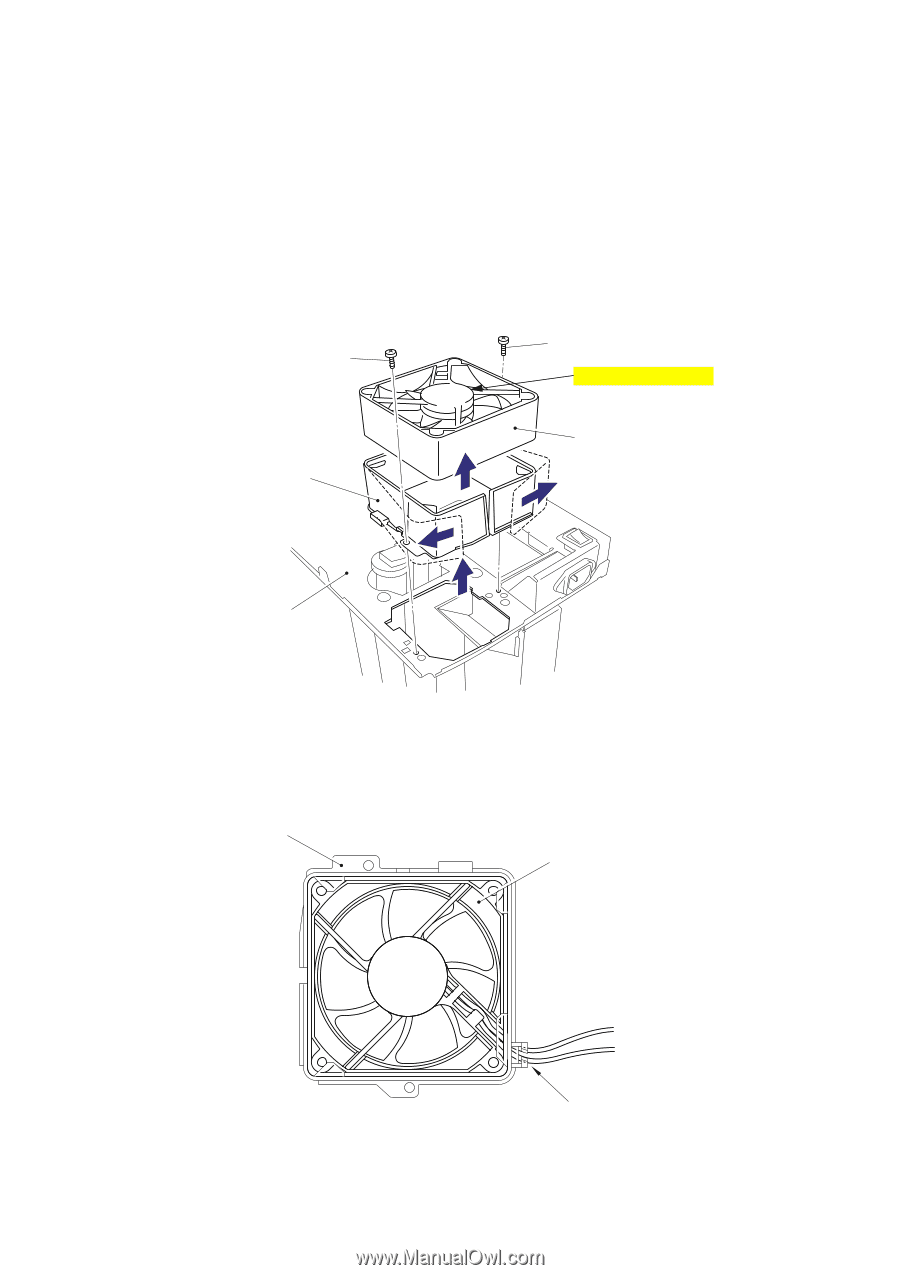
CHAPTER 4 DISASSEMBLY AND RE-ASSEMBLY 3.17 Fan Motor ASSY NOTE: Be sure to remove the fixing unit and disconnect the fan motor connector on the engine PCB before removing the fan motor ASSY. (1) Place the main frame so that the fan motor ASSY is at the top. (2) Remove the two M3x6 Taptite screws securing the fan cover. (3) Remove the fan motor ASSY with the fan cover and remove the fan motor ASSY from the cover. Taptite, cup M3x6 Taptite, cup M3x6 Manufacturer sticker side Fan cover Fan motor ASSY Main frame Fig. 4-58 NOTE: When re-assembling the fan motor, fix the harness into the groove on the motor, then fix the motor onto the bosses. Fan cover Fan motor Fig. 4-59 4-33 (groove)
-
 1
1 -
2
-
3
-
4
-
5
-
6
-
7
-
8
-
9
-
10
-
11
-
12
-
13
-
14
-
15
-
16
-
17
-
18
-
19
-
20
-
21
-
22
-
23
-
24
-
25
-
26
-
27
-
28
-
29
-
30
-
31
-
32
-
33
-
34
-
35
-
36
-
37
-
38
-
39
-
40
-
41
-
42
-
43
-
44
-
45
-
46
-
47
-
48
-
49
-
50
-
51
-
52
-
53
-
54
-
55
-
56
-
57
-
58
-
59
-
60
-
61
-
62
-
63
-
64
-
65
-
66
-
67
-
68
-
69
-
70
-
71
-
72
-
73
-
74
-
75
-
76
-
77
-
78
-
79
-
80
-
81
-
82
-
83
-
84
-
85
-
86
-
87
-
88
-
89
-
90
-
91
-
 92
92 -
 93
93 -
 94
94 -
 95
95 -
 96
96 -
 97
97 -
 98
98 -
 99
99 -
 100
100 -
 101
101 -
 102
102 -
103
-
104
-
105
-
106
-
107
-
108
-
109
-
110
-
111
-
112
-
113
-
114
-
115
-
116
-
117
-
118
-
119
-
120
-
121
-
122
-
123
-
124
-
125
-
126
-
127
-
128
-
129
-
130
-
131
-
132
-
133
-
134
-
135
-
136
-
137
-
138
-
139
-
140
-
141
-
142
-
143
-
144
-
145
-
146
-
147
-
148
-
149
-
150
-
151
-
152
-
153
-
154
-
155
-
156
-
157
-
158
-
159
-
160
-
161
-
162
-
163
-
164
-
165
-
166
-
167
-
168
-
169
-
170
-
171
-
172
-
173
-
174
-
175
-
176
-
177
-
178
-
179
-
180
-
181
-
182
-
183
-
184
-
185
-
186
-
187
-
188
-
189
-
190
-
191
-
192
-
193
-
194
-
195
-
196
-
197
-
198
-
199
-
200
-
201
-
202
-
203
-
204
-
205
-
206
-
207
-
208
-
209
-
210
-
211
-
212
-
213
-
214
-
215
-
216
-
217
-
218
-
219
-
220
-
221
-
222
-
223
-
224
-
225
-
226
-
227
-
228
-
229
-
230
-
231
-
232
-
233
-
234
-
235
-
236
-
237
-
238
-
239
-
240
-
241
-
242
-
243
-
244
-
245
-
246
-
247
-
248
-
249
-
250
-
251
-
252
-
253
-
254
-
255
-
256
-
257
-
258
-
259
-
260
-
261
-
262
-
263
-
264
-
265
-
266
-
267
-
268
-
269
-
270
-
271
-
272
-
273
-
274
-
275
-
276
-
277
-
278
-
279
-
280
-
281
-
282
-
283
-
284
-
285
-
286
-
287
-
288
-
289
-
290
-
291
-
292
-
293
-
294
-
295
-
296
-
297
-
298
-
299
-
300
-
301
-
302
-
303
-
304
-
305
-
306
-
307
-
308
-
309
-
310
-
311
-
312
-
313
-
314
-
315
-
316
-
317
-
318
-
319
-
320
-
321
-
322
-
323
-
324
-
325
-
326
-
327
-
328
-
329
-
330
-
331
-
332
-
333
 |
 |
CHAPTER 4
DISASSEMBLY AND RE-ASSEMBLY
4-33
3.17
Fan Motor ASSY
NOTE:
Be sure to remove the fixing unit and disconnect the fan motor connector on the engine PCB
before removing the fan motor ASSY.
(1)
Place the main frame so that the fan motor ASSY is at the top.
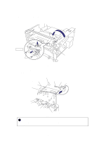
(2)
Remove the two M3x6 Taptite screws securing the fan cover.
(3)
Remove the fan motor ASSY with the fan cover and remove the fan motor ASSY from the
cover.
Fig. 4-58
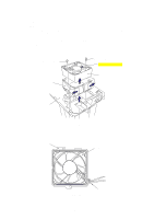
NOTE:
When re-assembling the fan motor, fix the harness into the groove on the motor, then fix the
motor onto the bosses.
Fig. 4-59
Taptite, cup M3x6
Taptite, cup M3x6
Fan motor ASSY
Fan cover
Main frame
Manufacturer sticker side
Fan cover
(groove)
Fan motor