Dell Brocade G620 Hardware Installation Guide - Page 14
License options, Port-side view - initial setup
 |
View all Dell Brocade G620 manuals
Add to My Manuals
Save this manual to your list of manuals |
Page 14 highlights
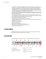
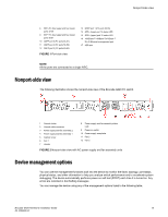
License options • One 10BASE-T / 100BASE-TX / 1000BASE-T RJ45 connector Ethernet port for management connection. In conjunction with EZSwitchSetup, this port supports switch IP address discovery and configuration, eliminating the need to attach a serial cable to configure the switch IP address. • One RS-232 3-wire (Tx, Rx, and Gnd) universal asynchronous receiver/transmitter (UART) serial port to BMC with RJ-45 connector for debugging initial switch setup (if not using EZSwitch Setup) and factory default restoration. Integral LEDs remain unlit at all times. • One internal e-USB module provides 2 GB of persistent storage, increased serviceability, and error logging functionality by facilitating easier firmware upgrades and downloads of the system log files. • One external USB connector. • Two hot-swappable redundant integrated power supply and fan assembly field-replaceable units. • 48 hot-pluggable SFP+ optical transceiver slots and 4 hot-pluggable QSFP optical transceiver slots. • 64 bicolor (green/amber) LEDs to indicate the status for each port. • One green LED to indicate valid system power. • One bicolor (green/amber) LED to indicate the system status. • Two Ethernet LEDs: one bicolor (green/amber) LED to indicate link at 1000/100/10 Mbps and one green LED to indicate activity. • SEEPROM for switch identification. • Real-time power monitoring. • Real-time voltage monitoring. • Real-time fan monitoring including airflow direction. • Real-time digital thermometers for temperature monitoring. • Real-time clock (RTC) with battery. License options The Brocade G620 uses a capacity-based Ports on Demand (POD) license method. Refer to the Brocade Fabric OS Software Licensing Guide for more details. Port-side view The following illustration shows the port-side view of the Brocade G620 Fibre Channel switch. 1 System status LED 2 System power LED 3 UART RJ-45 serial console port 4 SFP+ FC (four upper and four lower) ports 0-7 5 SFP+ FC (four upper and four lower) ports 8-15 6 SFP+ FC (four upper and four lower) ports 16-23 7 SFP+ FC (four upper and four lower) ports 24-31 14 Brocade G620 Hardware Installation Guide 53-1003990-01
-
 1
1 -
2
-
3
-
4
-
5
-
6
-
7
-
8
-
 9
9 -
 10
10 -
 11
11 -
 12
12 -
 13
13 -
 14
14 -
 15
15 -
 16
16 -
 17
17 -
 18
18 -
 19
19 -
20
-
21
-
22
-
23
-
24
-
25
-
26
-
27
-
28
-
29
-
30
-
31
-
32
-
33
-
34
-
35
-
36
-
37
-
38
-
39
-
40
-
41
-
42
-
43
-
44
-
45
-
46
-
47
-
48
-
49
-
50
-
51
-
52
-
53
-
54
-
55
-
56
-
57
-
58
-
59
-
60
-
61
-
62
-
63
-
64
-
65
-
66
-
67
-
68
-
69
-
70
-
71
-
72
-
73
-
74
-
75
-
76
-
77
-
78
-
79
-
80
-
81
-
82
-
83
-
84
-
85
-
86
-
87
-
88
-
89
-
90
-
91
-
92
-
93
-
94
-
95
-
96
-
97
-
98
-
99
-
100
-
101
-
102
-
103
-
104
 |
 |
