Dell Brocade G620 Hardware Installation Guide - Page 15
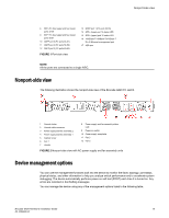
Nonport-side view, Device management options
 |
View all Dell Brocade G620 manuals
Add to My Manuals
Save this manual to your list of manuals |
Page 15 highlights
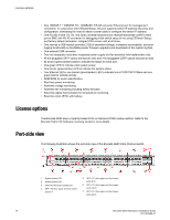
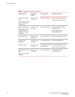
Nonport-side view 8 SFP+ FC (four upper and four lower) ports 32-39 9 SFP+ FC (four upper and four lower) ports 40-47 10 QSFP port 0 (FC ports 48-51) 11 QSFP port 2 (FC ports 56-59) 12 QSFP port 3 (FC ports 60-63) FIGURE 1 Port-side view 13 QSFP port 1 (FC ports 52-55) 14 SFP+ (lower) port 14 status LED 15 SFP+ (upper) port 10 status LED 16 1000Base-T/100Base-TX/10Base-T RJ-45 Ethernet management port 17 USB port NOTE All the ports are connected to a single ASIC. Nonport-side view The following illustration shows the nonport-side view of the Brocade G620 FC switch. 1 Ground sticker 2 Ground cable connector 3 Power supply and fan assembly 2 4 Power supply and fan assembly 1 5 Captive screw 6 Fan 1 7 Handle 8 Power supply and fan assembly status LED 9 Power-on switch 10 Power supply receptacle 11 Fan 2 12 Fan 3 FIGURE 2 Nonport-side view with AC power supply and fan assembly units Device management options You can use the management functions built into the device to monitor the fabric topology, port status, physical status, and other information to help you analyze switch performance and to accelerate system debugging. The device automatically performs power-on self-test (POST) each time it is turned on. Any errors are recorded in the RASlog messages. You can manage the device using any of the management options listed in the following table. Brocade G620 Hardware Installation Guide 15 53-1003990-01
-
 1
1 -
2
-
3
-
4
-
5
-
6
-
7
-
8
-
9
-
 10
10 -
 11
11 -
 12
12 -
 13
13 -
 14
14 -
 15
15 -
 16
16 -
 17
17 -
 18
18 -
 19
19 -
 20
20 -
21
-
22
-
23
-
24
-
25
-
26
-
27
-
28
-
29
-
30
-
31
-
32
-
33
-
34
-
35
-
36
-
37
-
38
-
39
-
40
-
41
-
42
-
43
-
44
-
45
-
46
-
47
-
48
-
49
-
50
-
51
-
52
-
53
-
54
-
55
-
56
-
57
-
58
-
59
-
60
-
61
-
62
-
63
-
64
-
65
-
66
-
67
-
68
-
69
-
70
-
71
-
72
-
73
-
74
-
75
-
76
-
77
-
78
-
79
-
80
-
81
-
82
-
83
-
84
-
85
-
86
-
87
-
88
-
89
-
90
-
91
-
92
-
93
-
94
-
95
-
96
-
97
-
98
-
99
-
100
-
101
-
102
-
103
-
104
 |
 |
