Dell OptiPlex GX1 Dell OptiPlex GX1/GX1p Managed PC and OptiPlex NX1 Net PC S - Page 128
following sub s.
 |
View all Dell OptiPlex GX1 manuals
Add to My Manuals
Save this manual to your list of manuals |
Page 128 highlights
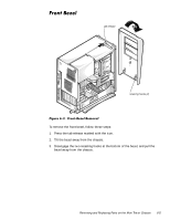
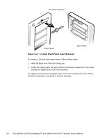
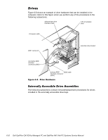
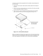
Figure 6-8 shows an example of drive hardware that can be installed in the computer. Refer to this figure when you perform any of the procedures in the following subsections. diskette/tape drive interface cable 3.5-inch diskette drive DC power cable DSKT connector secondary EIDE interface connector (IDE2) hard-disk drive bracket primary EIDE EIDE cable interface connector (IDE1) The following subsections contain removal/replacement procedures for drives installed in the externally accessible drive bays. 6-10
-
 1
1 -
2
-
3
-
4
-
5
-
6
-
7
-
8
-
9
-
10
-
11
-
12
-
13
-
14
-
15
-
16
-
17
-
18
-
19
-
20
-
21
-
22
-
23
-
24
-
25
-
26
-
27
-
28
-
29
-
30
-
31
-
32
-
33
-
34
-
35
-
36
-
37
-
38
-
39
-
40
-
41
-
42
-
43
-
44
-
45
-
46
-
47
-
48
-
49
-
50
-
51
-
52
-
53
-
54
-
55
-
56
-
57
-
58
-
59
-
60
-
61
-
62
-
63
-
64
-
65
-
66
-
67
-
68
-
69
-
70
-
71
-
72
-
73
-
74
-
75
-
76
-
77
-
78
-
79
-
80
-
81
-
82
-
83
-
84
-
85
-
86
-
87
-
88
-
89
-
90
-
91
-
92
-
93
-
94
-
95
-
96
-
97
-
98
-
99
-
100
-
101
-
102
-
103
-
104
-
105
-
106
-
107
-
108
-
109
-
110
-
111
-
112
-
113
-
114
-
115
-
116
-
117
-
118
-
119
-
120
-
121
-
122
-
 123
123 -
 124
124 -
 125
125 -
 126
126 -
 127
127 -
 128
128 -
 129
129 -
 130
130 -
 131
131 -
 132
132 -
 133
133 -
134
-
135
-
136
-
137
-
138
-
139
-
140
-
141
-
142
-
143
-
144
-
145
-
146
-
147
-
148
-
149
-
150
-
151
-
152
-
153
-
154
-
155
-
156
-
157
-
158
-
159
-
160
-
161
-
162
-
163
-
164
-
165
-
166
-
167
-
168
-
169
-
170
-
171
-
172
-
173
-
174
-
175
-
176
-
177
-
178
 |
 |

6-10
’HOO±2SWL3OH[±*;²³*;²S±0DQDJHG±3&±DQG±2SWL3OH[±1;²±1HW±3&±6\VWHPV±6HUYLFH±0DQXDO
’ULYHV
Figure 6-8 shows an example of drive hardware that can be installed in the
computer. Refer to this figure when you perform any of the procedures in the
following subsections.
)LJXUH±¹´À³±±’ULYH±+DUGZDUH
([WHUQDOO\±$FFHVVLEOH±’ULYH±$VVHPEOLHV
The following subsections contain removal/replacement procedures for drives
installed in the externally accessible drive bays.
diskette/tape drive
interface cable
DC power cable
DSKT connector
hard-disk drive bracket
primary EIDE
interface connector
(IDE1)
secondary EIDE
interface
connector (IDE2)
EIDE cable
3.5-inch diskette
drive