Dell OptiPlex GX1 Dell OptiPlex GX1/GX1p Managed PC and OptiPlex NX1 Net PC S - Page 74
connect any telephone or telecommunication lines from
 |
View all Dell OptiPlex GX1 manuals
Add to My Manuals
Save this manual to your list of manuals |
Page 74 highlights
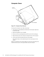
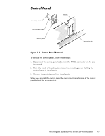
1. Turn off the computer and any attached peripherals. 2. Disconnect the computer and any attached peripherals from their power sources to reduce the potential for personal injury. Also, disconnect any telephone or telecommunication lines from the computer. 3. Wait 5 seconds after powering down the computer before disconnecting a peripheral from the computer or removing a component from the computer's system board to avoid possible damage to the system board. Figure 4-1 shows an internal view of the interior of the low-profile computer and identifies major components for orientation. Refer to this illustration, as needed, when performing the component removal/replacement procedures in this chapter. 4-2
-
 1
1 -
2
-
3
-
4
-
5
-
6
-
7
-
8
-
9
-
10
-
11
-
12
-
13
-
14
-
15
-
16
-
17
-
18
-
19
-
20
-
21
-
22
-
23
-
24
-
25
-
26
-
27
-
28
-
29
-
30
-
31
-
32
-
33
-
34
-
35
-
36
-
37
-
38
-
39
-
40
-
41
-
42
-
43
-
44
-
45
-
46
-
47
-
48
-
49
-
50
-
51
-
52
-
53
-
54
-
55
-
56
-
57
-
58
-
59
-
60
-
61
-
62
-
63
-
64
-
65
-
66
-
67
-
68
-
 69
69 -
 70
70 -
 71
71 -
 72
72 -
 73
73 -
 74
74 -
 75
75 -
 76
76 -
 77
77 -
 78
78 -
 79
79 -
80
-
81
-
82
-
83
-
84
-
85
-
86
-
87
-
88
-
89
-
90
-
91
-
92
-
93
-
94
-
95
-
96
-
97
-
98
-
99
-
100
-
101
-
102
-
103
-
104
-
105
-
106
-
107
-
108
-
109
-
110
-
111
-
112
-
113
-
114
-
115
-
116
-
117
-
118
-
119
-
120
-
121
-
122
-
123
-
124
-
125
-
126
-
127
-
128
-
129
-
130
-
131
-
132
-
133
-
134
-
135
-
136
-
137
-
138
-
139
-
140
-
141
-
142
-
143
-
144
-
145
-
146
-
147
-
148
-
149
-
150
-
151
-
152
-
153
-
154
-
155
-
156
-
157
-
158
-
159
-
160
-
161
-
162
-
163
-
164
-
165
-
166
-
167
-
168
-
169
-
170
-
171
-
172
-
173
-
174
-
175
-
176
-
177
-
178
 |
 |

4-2
’HOO±2SWL3OH[±*;²³*;²S±0DQDJHG±3&±DQG±2SWL3OH[±1;²±1HW±3&±6\VWHPV±6HUYLFH±0DQXDO
:$51,1*²)25²<285²3(5621$/²6$)(7<²$1’²3527(&7,21²2)²7+(²
(48,30(17²
%HIRUH²\RX²VWDUW²WR²ZRUN²RQ²WKH²V\VWHP¶²SHUIRUP²WKH²IROORZLQJ²VWHSV²
LQ²WKH²VHTXHQFH²OLVWHG±²
1.
Turn off the computer and any attached peripherals.
2.
Disconnect the computer and any attached peripherals from their
power sources to reduce the potential for personal injury. Also, dis-
connect any telephone or telecommunication lines from the
computer.
3.
Wait 5 seconds after powering down the computer before
disconnecting a peripheral from the computer or removing a
component from the computer’s system board to avoid possible dam-
age to the system board.
:HDU²D²ZULVW²JURXQGLQJ²VWUDS¶²DQG²FOLS²LW²WR²DQ²XQSDLQWHG²PHWDO²VXU´
IDFH¶²VXFK²DV²WKH²SDGORFN²ORRS²RQ²WKH²EDFN²RI²WKH²FKDVVLV³²,I²D²ZULVW²
JURXQGLQJ²VWUDS²LV²QRW²DYDLODEOH¶²SHULRGLFDOO\
±
WRXFK
±
DQ²XQSDLQWHG²
PHWDO²VXUIDFH²RQ²WKH²EDFN²RI²WKH²FRPSXWHU²WR²GLVFKDUJH²DQ\²VWDWLF²
FKDUJH²IURP²\RXU²ERG\³²$YRLG²WRXFKLQJ²FRPSRQHQWV²DQG²FRQWDFWV²RQ²
D²FDUG¶²DQG²DYRLG²WRXFKLQJ²SLQV²RQ²D²FKLS²WR²SUHYHQW²VWDWLF²HOHFWULFLW\²
GDPDJH³
,QVLGH±WKH±&RPSXWHU
Figure 4-1 shows an internal view of the interior of the low-profile computer
and identifies major components for orientation. Refer to this illustration, as
needed, when performing the component removal/replacement procedures in
this chapter.