Dell OptiPlex GX1 Dell OptiPlex GX1/GX1p Managed PC and OptiPlex NX1 Net PC S - Page 45
Power-supply connector identification
 |
View all Dell OptiPlex GX1 manuals
Add to My Manuals
Save this manual to your list of manuals |
Page 45 highlights
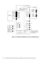
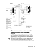
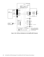
P2 1 2 34 5 6 +3.3 VDC (blue/white) +3.3 VDC (blue/white) +3.3 VDC (blue/white) common (black) common (black) common (black) 1234 P3 +5 VDC (red) common (black) common (black) +12 VDC (yellow) Figures 1-27 and 1-28 provide the following information about DC power distribution: Power-supply connector identification Power cable connection for the hard-disk drive Power distribution to sockets and connectors on the system board P3 P2 P1 System Overview 1-33
-
 1
1 -
2
-
3
-
4
-
5
-
6
-
7
-
8
-
9
-
10
-
11
-
12
-
13
-
14
-
15
-
16
-
17
-
18
-
19
-
20
-
21
-
22
-
23
-
24
-
25
-
26
-
27
-
28
-
29
-
30
-
31
-
32
-
33
-
34
-
35
-
36
-
37
-
38
-
39
-
 40
40 -
 41
41 -
 42
42 -
 43
43 -
 44
44 -
 45
45 -
 46
46 -
 47
47 -
 48
48 -
 49
49 -
 50
50 -
51
-
52
-
53
-
54
-
55
-
56
-
57
-
58
-
59
-
60
-
61
-
62
-
63
-
64
-
65
-
66
-
67
-
68
-
69
-
70
-
71
-
72
-
73
-
74
-
75
-
76
-
77
-
78
-
79
-
80
-
81
-
82
-
83
-
84
-
85
-
86
-
87
-
88
-
89
-
90
-
91
-
92
-
93
-
94
-
95
-
96
-
97
-
98
-
99
-
100
-
101
-
102
-
103
-
104
-
105
-
106
-
107
-
108
-
109
-
110
-
111
-
112
-
113
-
114
-
115
-
116
-
117
-
118
-
119
-
120
-
121
-
122
-
123
-
124
-
125
-
126
-
127
-
128
-
129
-
130
-
131
-
132
-
133
-
134
-
135
-
136
-
137
-
138
-
139
-
140
-
141
-
142
-
143
-
144
-
145
-
146
-
147
-
148
-
149
-
150
-
151
-
152
-
153
-
154
-
155
-
156
-
157
-
158
-
159
-
160
-
161
-
162
-
163
-
164
-
165
-
166
-
167
-
168
-
169
-
170
-
171
-
172
-
173
-
174
-
175
-
176
-
177
-
178
 |
 |

System Overview
1-33
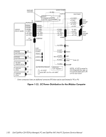
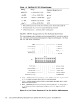
)LJXUH±²´µ¸³±±’&±3RZHU±&RQQHFWRU±3µ±IRU±WKH±2SWL3OH[±1;²±&RPSXWHU
)LJXUH±²´µ¹³±±’&±3RZHU±&RQQHFWRU±3¶±IRU±WKH±2SWL3OH[±1;²±&RPSXWHU
’&±3RZHU±’LVWULEXWLRQ±IRU±WKH±2SWL3OH[±1;µ±&RPSXWHU
Figures 1-27 and 1-28 provide the following information about DC power
distribution:
¼
Power-supply connector identification
¼
Power cable connection for the hard-disk drive
¼
Power distribution to sockets and connectors on the system board
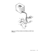
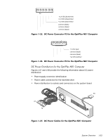
)LJXUH±²´µº³±±’&±3RZHU±&DEOHV±IRU±WKH±2SWL3OH[±1;²±&RPSXWHU
1
2
3
4
+3.3 VDC (blue/white)
common (black)
common (black)
5
P2
6
+3.3 VDC (blue/white)
+3.3 VDC (blue/white)
common (black)
1
2
3
4
+5 VDC (red)
common (black)
common (black)
+12 VDC (yellow)
P3
P3
P2
P1