Dell OptiPlex GX1 Dell OptiPlex GX1/GX1p Managed PC and OptiPlex NX1 Net PC S - Page 63
Dell OptiPlex GX1 Manual
 |
View all Dell OptiPlex GX1 manuals
Add to My Manuals
Save this manual to your list of manuals |
Page 63 highlights
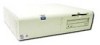
kit connected to the computer as shown in Figure 2-1 and described in the following procedure. The diskette-based diagnostics contains the same tests as the hard-disk- based diagnostics. These tests aid in troubleshooting all major components of the system. hard-disk drive external diskette drive diskette drive connector Y-cable P3 connector interface cable To install the external diskette drive, follow these steps: 1. Turn off the computer, including any attached peripherals, and disconnect all the AC power cables from their power sources. 2. Disconnect power input connector P3 from the back of the hard-disk drive. 3. Connect the interface cable to the back of the external diskette drive (see Figure 2-1) and to the DSKT connector on the system board (see Figure 1-12). 4. Attach the Y-cable to power input connector P3 as shown in Figure 2-1. 5. Connect the Y-cable's hard-disk drive connector to the hard-disk drive. 6. Connect the Y-cable's diskette drive connector to the back of the external diskette drive. Basic Troubleshooting 2-9
-
 1
1 -
2
-
3
-
4
-
5
-
6
-
7
-
8
-
9
-
10
-
11
-
12
-
13
-
14
-
15
-
16
-
17
-
18
-
19
-
20
-
21
-
22
-
23
-
24
-
25
-
26
-
27
-
28
-
29
-
30
-
31
-
32
-
33
-
34
-
35
-
36
-
37
-
38
-
39
-
40
-
41
-
42
-
43
-
44
-
45
-
46
-
47
-
48
-
49
-
50
-
51
-
52
-
53
-
54
-
55
-
56
-
57
-
 58
58 -
 59
59 -
 60
60 -
 61
61 -
 62
62 -
 63
63 -
 64
64 -
 65
65 -
 66
66 -
 67
67 -
 68
68 -
69
-
70
-
71
-
72
-
73
-
74
-
75
-
76
-
77
-
78
-
79
-
80
-
81
-
82
-
83
-
84
-
85
-
86
-
87
-
88
-
89
-
90
-
91
-
92
-
93
-
94
-
95
-
96
-
97
-
98
-
99
-
100
-
101
-
102
-
103
-
104
-
105
-
106
-
107
-
108
-
109
-
110
-
111
-
112
-
113
-
114
-
115
-
116
-
117
-
118
-
119
-
120
-
121
-
122
-
123
-
124
-
125
-
126
-
127
-
128
-
129
-
130
-
131
-
132
-
133
-
134
-
135
-
136
-
137
-
138
-
139
-
140
-
141
-
142
-
143
-
144
-
145
-
146
-
147
-
148
-
149
-
150
-
151
-
152
-
153
-
154
-
155
-
156
-
157
-
158
-
159
-
160
-
161
-
162
-
163
-
164
-
165
-
166
-
167
-
168
-
169
-
170
-
171
-
172
-
173
-
174
-
175
-
176
-
177
-
178
 |
 |