Dell OptiPlex GX1 Dell OptiPlex GX1/GX1p Managed PC and OptiPlex NX1 Net PC S - Page 156
NOTES: If you are replacing a system board, remove the microprocessor/heat
 |
View all Dell OptiPlex GX1 manuals
Add to My Manuals
Save this manual to your list of manuals |
Page 156 highlights
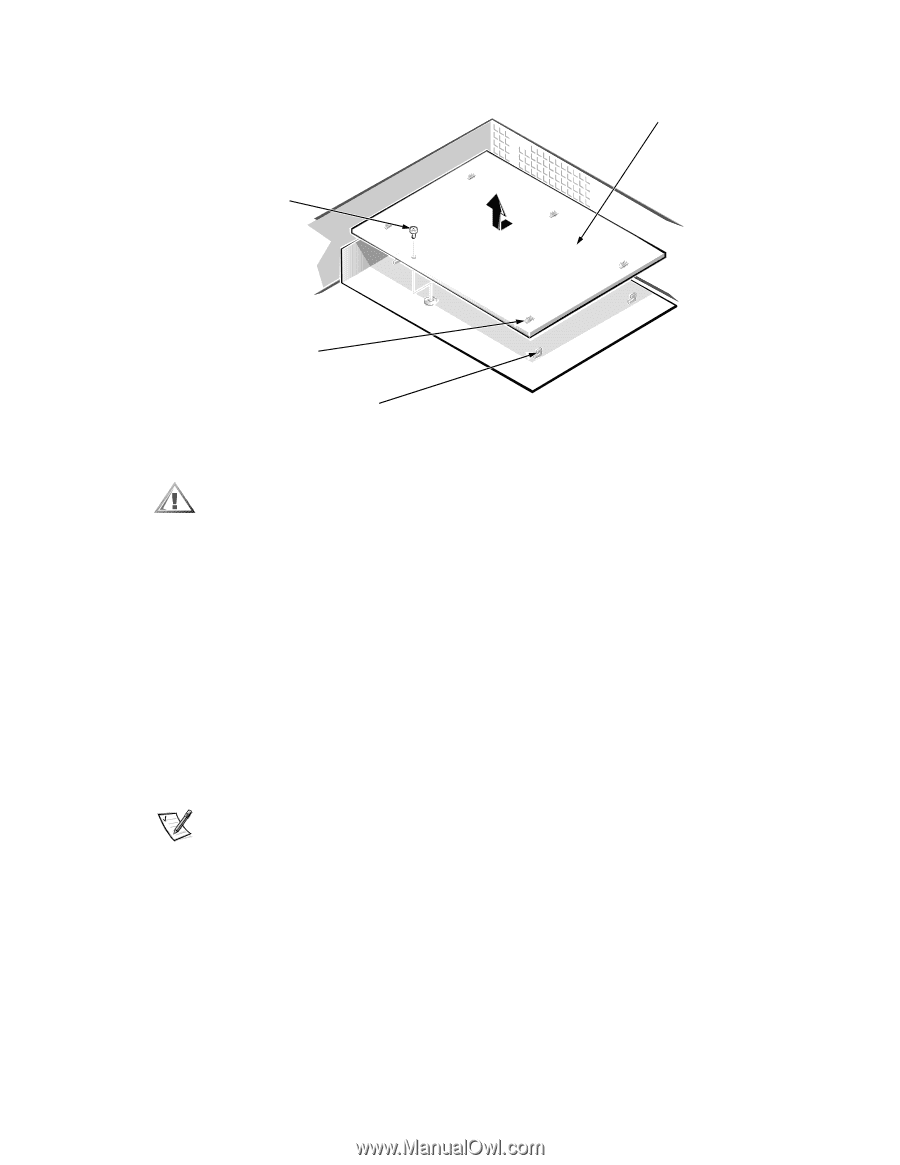
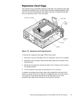
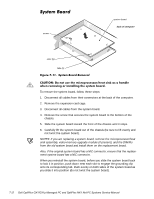
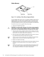
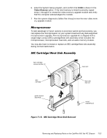
screw system board back of computer slots (5) tabs (5) To remove the system board, follow these steps: 1. Disconnect all cables from their connectors at the back of the computer. 2. Remove the expansion-card cage. 3. Disconnect all cables from the system board. 4. Remove the screw that secures the system board to the bottom of the chassis. 5. Slide the system board toward the front of the chassis until it stops. 6. Carefully lift the system board out of the chassis (be sure to lift evenly and not twist the system board). NOTES: If you are replacing a system board, remove the microprocessor/heat sink assembly, video-memory upgrade module (if present), and the DIMMs from the old system board and install them on the replacement board. Also, if the original system board has a NIC connector, ensure that the replacement system board has a NIC connector. When you reinstall the system board, before you slide the system board back to lock it in position, push down near each slot to engage the grounding clip onto its corresponding tab. Push evenly on both sides of the system board as you slide it into position (do not twist the system board). 7-12
-
 1
1 -
2
-
3
-
4
-
5
-
6
-
7
-
8
-
9
-
10
-
11
-
12
-
13
-
14
-
15
-
16
-
17
-
18
-
19
-
20
-
21
-
22
-
23
-
24
-
25
-
26
-
27
-
28
-
29
-
30
-
31
-
32
-
33
-
34
-
35
-
36
-
37
-
38
-
39
-
40
-
41
-
42
-
43
-
44
-
45
-
46
-
47
-
48
-
49
-
50
-
51
-
52
-
53
-
54
-
55
-
56
-
57
-
58
-
59
-
60
-
61
-
62
-
63
-
64
-
65
-
66
-
67
-
68
-
69
-
70
-
71
-
72
-
73
-
74
-
75
-
76
-
77
-
78
-
79
-
80
-
81
-
82
-
83
-
84
-
85
-
86
-
87
-
88
-
89
-
90
-
91
-
92
-
93
-
94
-
95
-
96
-
97
-
98
-
99
-
100
-
101
-
102
-
103
-
104
-
105
-
106
-
107
-
108
-
109
-
110
-
111
-
112
-
113
-
114
-
115
-
116
-
117
-
118
-
119
-
120
-
121
-
122
-
123
-
124
-
125
-
126
-
127
-
128
-
129
-
130
-
131
-
132
-
133
-
134
-
135
-
136
-
137
-
138
-
139
-
140
-
141
-
142
-
143
-
144
-
145
-
146
-
147
-
148
-
149
-
150
-
 151
151 -
 152
152 -
 153
153 -
 154
154 -
 155
155 -
 156
156 -
 157
157 -
 158
158 -
 159
159 -
 160
160 -
 161
161 -
162
-
163
-
164
-
165
-
166
-
167
-
168
-
169
-
170
-
171
-
172
-
173
-
174
-
175
-
176
-
177
-
178
 |
 |