Dell PowerEdge R240 EMC PowerEdge R240 Installation and Service Manual - Page 36
Recommended tools, Front bezel, Removing the front bezel
 |
View all Dell PowerEdge R240 manuals
Add to My Manuals
Save this manual to your list of manuals |
Page 36 highlights
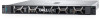
4. Power on the attached peripherals and then power on the system. Recommended tools You need the following tools to perform the removal and installation procedures: • Key to the bezel lock The key is required only if your system includes a bezel. • Phillips #1 screwdriver • Phillips #2 screwdriver • Torx #T15 screwdriver • Plastic scribe • 1/4 inch flat blade screwdriver • Wrist grounding strap connected to the ground • ESD mat You need the following tools to assemble the cables for a DC power supply unit: • AMP 90871-1 hand-crimping tool or equivalent • Tyco Electronics 58433-3 or equivalent • Wire-stripper pliers to remove insulation from size 10 AWG solid or stranded, insulated copper wire NOTE: Use alpha wire part number 3080 or equivalent (65/30 stranding). Front bezel Removing the front bezel Prerequisites 1. Follow the safety guidelines listed in the Safety instructions. 2. Keep the bezel key handy. Steps 1. Unlock the bezel. 2. Press the release button, and remove the left end of the bezel. 3. Unhook the right end of the bezel, and remove the bezel. Figure 9. Removing the front bezel 36 PowerEdge R240 installing and removing system components
-
 1
1 -
2
-
3
-
4
-
5
-
6
-
7
-
8
-
9
-
10
-
11
-
12
-
13
-
14
-
15
-
16
-
17
-
18
-
19
-
20
-
21
-
22
-
23
-
24
-
25
-
26
-
27
-
28
-
29
-
30
-
 31
31 -
 32
32 -
 33
33 -
 34
34 -
 35
35 -
 36
36 -
 37
37 -
 38
38 -
 39
39 -
 40
40 -
 41
41 -
42
-
43
-
44
-
45
-
46
-
47
-
48
-
49
-
50
-
51
-
52
-
53
-
54
-
55
-
56
-
57
-
58
-
59
-
60
-
61
-
62
-
63
-
64
-
65
-
66
-
67
-
68
-
69
-
70
-
71
-
72
-
73
-
74
-
75
-
76
-
77
-
78
-
79
-
80
-
81
-
82
-
83
-
84
-
85
-
86
-
87
-
88
-
89
-
90
-
91
-
92
-
93
-
94
-
95
-
96
-
97
-
98
-
99
-
100
-
101
-
102
-
103
-
104
-
105
-
106
-
107
-
108
-
109
-
110
-
111
-
112
-
113
-
114
 |
 |
