Dell PowerEdge R240 EMC PowerEdge R240 Installation and Service Manual - Page 55
System memory, System memory guidelines
 |
View all Dell PowerEdge R240 manuals
Add to My Manuals
Save this manual to your list of manuals |
Page 55 highlights
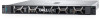
Figure 34. Installing the intrusion switch Next steps 1. Follow the procedure listed in the After working inside your system. System memory System memory guidelines Your system contains 4 memory sockets organized into two channels. In each channel, the 1st socket is marked white and the 2nd socket black. PowerEdge R240 installing and removing system components 55
-
 1
1 -
2
-
3
-
4
-
5
-
6
-
7
-
8
-
9
-
10
-
11
-
12
-
13
-
14
-
15
-
16
-
17
-
18
-
19
-
20
-
21
-
22
-
23
-
24
-
25
-
26
-
27
-
28
-
29
-
30
-
31
-
32
-
33
-
34
-
35
-
36
-
37
-
38
-
39
-
40
-
41
-
42
-
43
-
44
-
45
-
46
-
47
-
48
-
49
-
 50
50 -
 51
51 -
 52
52 -
 53
53 -
 54
54 -
 55
55 -
 56
56 -
 57
57 -
 58
58 -
 59
59 -
 60
60 -
61
-
62
-
63
-
64
-
65
-
66
-
67
-
68
-
69
-
70
-
71
-
72
-
73
-
74
-
75
-
76
-
77
-
78
-
79
-
80
-
81
-
82
-
83
-
84
-
85
-
86
-
87
-
88
-
89
-
90
-
91
-
92
-
93
-
94
-
95
-
96
-
97
-
98
-
99
-
100
-
101
-
102
-
103
-
104
-
105
-
106
-
107
-
108
-
109
-
110
-
111
-
112
-
113
-
114
 |
 |

Figure 34. Installing the intrusion switch
Next steps
1.
Follow the procedure listed in the
After working inside your system
.
System memory
System memory guidelines
Your system contains 4 memory sockets organized into two channels. In each channel, the 1st socket is marked white and the 2nd socket
black.
PowerEdge R240 installing and removing system components
55