Dell PowerEdge R6525 EMC Installation and Service Manual - Page 111
Installing the serial COM port
 |
View all Dell PowerEdge R6525 manuals
Add to My Manuals
Save this manual to your list of manuals |
Page 111 highlights
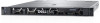
Figure 89. Removing the serial COM port Next steps 1. Replace the serial COM port. Installing the serial COM port Prerequisites 1. Follow the safety guidelines listed in the Safety instructions on page 42. 2. Follow the procedure listed in Before working inside your system on page 43. 3. Lift the expansion card riser and disconnect the serial COM port cable from the connector on the rear I/O board. Steps 1. Open the latch on the expansion card riser and remove the filler bracket from the expansion card riser (Riser 3). NOTE: For more information about how to remove the filler bracket, see the Removing the expansion card from the expansion card riser topic. 2. Slide the serial COM port into the expansion card riser. 3. Connect the serial COM port cable to the serial port. 4. Connect the serial COM port cable to the connector on the rear I/O board. NOTE: The numbers on the image do not depict the exact steps. The numbers are for representation of sequence. Installing and removing system components 111
-
 1
1 -
2
-
3
-
4
-
5
-
6
-
7
-
8
-
9
-
10
-
11
-
12
-
13
-
14
-
15
-
16
-
17
-
18
-
19
-
20
-
21
-
22
-
23
-
24
-
25
-
26
-
27
-
28
-
29
-
30
-
31
-
32
-
33
-
34
-
35
-
36
-
37
-
38
-
39
-
40
-
41
-
42
-
43
-
44
-
45
-
46
-
47
-
48
-
49
-
50
-
51
-
52
-
53
-
54
-
55
-
56
-
57
-
58
-
59
-
60
-
61
-
62
-
63
-
64
-
65
-
66
-
67
-
68
-
69
-
70
-
71
-
72
-
73
-
74
-
75
-
76
-
77
-
78
-
79
-
80
-
81
-
82
-
83
-
84
-
85
-
86
-
87
-
88
-
89
-
90
-
91
-
92
-
93
-
94
-
95
-
96
-
97
-
98
-
99
-
100
-
101
-
102
-
103
-
104
-
105
-
 106
106 -
 107
107 -
 108
108 -
 109
109 -
 110
110 -
 111
111 -
 112
112 -
 113
113 -
 114
114 -
 115
115 -
 116
116 -
117
-
118
-
119
-
120
-
121
-
122
-
123
-
124
-
125
-
126
-
127
-
128
-
129
-
130
-
131
-
132
-
133
-
134
-
135
-
136
-
137
-
138
-
139
-
140
-
141
-
142
-
143
-
144
-
145
-
146
-
147
-
148
-
149
-
150
-
151
-
152
-
153
-
154
-
155
-
156
-
157
-
158
-
159
-
160
-
161
-
162
-
163
-
164
 |
 |
