Dell PowerEdge R6525 EMC Installation and Service Manual - Page 53
Installing the VGA module
 |
View all Dell PowerEdge R6525 manuals
Add to My Manuals
Save this manual to your list of manuals |
Page 53 highlights
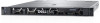
2. Slide the VGA module out of the system. NOTE: The numbers on the image do not depict the exact steps. The numbers are for representation of sequence. Figure 25. Removing the VGA module Next steps 1. Replace the VGA module. Installing the VGA module Prerequisites 1. Follow the safety guidelines listed in the Safety instructions on page 42. 2. Follow the procedure listed in the Before working inside your system on page 43. 3. If installed, remove the front bezel. 4. Remove the backplane cover. 5. If installed, remove the air shroud. 6. Disconnect the VGA cable from the connector on the system board. 7. Pull the right control panel cable from the clip and move it to clear the path of the see the VGA module screw. NOTE: Ensure that you note the routing of the cables as you remove them from the system board. Route the cable properly when you replace it to prevent the cable from being pinched or crimped Steps 1. Route the VGA cable through the slot on the front of the system and slide the VGA module into the slot. 2. Align the hole on the module with the screw hole on the system. 3. Using the Phillips #2 screwdriver, secure the VGA module to the system with the screw. Installing and removing system components 53
-
 1
1 -
2
-
3
-
4
-
5
-
6
-
7
-
8
-
9
-
10
-
11
-
12
-
13
-
14
-
15
-
16
-
17
-
18
-
19
-
20
-
21
-
22
-
23
-
24
-
25
-
26
-
27
-
28
-
29
-
30
-
31
-
32
-
33
-
34
-
35
-
36
-
37
-
38
-
39
-
40
-
41
-
42
-
43
-
44
-
45
-
46
-
47
-
 48
48 -
 49
49 -
 50
50 -
 51
51 -
 52
52 -
 53
53 -
 54
54 -
 55
55 -
 56
56 -
 57
57 -
 58
58 -
59
-
60
-
61
-
62
-
63
-
64
-
65
-
66
-
67
-
68
-
69
-
70
-
71
-
72
-
73
-
74
-
75
-
76
-
77
-
78
-
79
-
80
-
81
-
82
-
83
-
84
-
85
-
86
-
87
-
88
-
89
-
90
-
91
-
92
-
93
-
94
-
95
-
96
-
97
-
98
-
99
-
100
-
101
-
102
-
103
-
104
-
105
-
106
-
107
-
108
-
109
-
110
-
111
-
112
-
113
-
114
-
115
-
116
-
117
-
118
-
119
-
120
-
121
-
122
-
123
-
124
-
125
-
126
-
127
-
128
-
129
-
130
-
131
-
132
-
133
-
134
-
135
-
136
-
137
-
138
-
139
-
140
-
141
-
142
-
143
-
144
-
145
-
146
-
147
-
148
-
149
-
150
-
151
-
152
-
153
-
154
-
155
-
156
-
157
-
158
-
159
-
160
-
161
-
162
-
163
-
164
 |
 |
