Dell PowerEdge T550 EMC Installation and Service Manual - Page 146
To avoid damaging the fins on the heat sink, do not press down on the heat sink fins.
 |
View all Dell PowerEdge T550 manuals
Add to My Manuals
Save this manual to your list of manuals |
Page 146 highlights
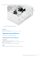
2. Align the pin 1 indicator of the heat sink to the system board, and then place the processor heat sink module (PHM) on the processor socket. CAUTION: To avoid damaging the fins on the heat sink, do not press down on the heat sink fins. NOTE: Ensure that the PHM is held parallel to the system board to prevent damaging the components. Figure 149. Installing the processor heat sink 3. Set the anti-tilt wires to the locked position (outward position), and then using the Torx T30 tool, tighten the nuts (12 in-lbf) on the PHM: a. Tighten the first nut three turns. b. Tighten the nut diagonally opposite to the nut you tighten first. c. Repeat the procedure for the remaining two nuts. d. Return to the first nut to tighten it completely. 146 Installing and removing system components
-
 1
1 -
2
-
3
-
4
-
5
-
6
-
7
-
8
-
9
-
10
-
11
-
12
-
13
-
14
-
15
-
16
-
17
-
18
-
19
-
20
-
21
-
22
-
23
-
24
-
25
-
26
-
27
-
28
-
29
-
30
-
31
-
32
-
33
-
34
-
35
-
36
-
37
-
38
-
39
-
40
-
41
-
42
-
43
-
44
-
45
-
46
-
47
-
48
-
49
-
50
-
51
-
52
-
53
-
54
-
55
-
56
-
57
-
58
-
59
-
60
-
61
-
62
-
63
-
64
-
65
-
66
-
67
-
68
-
69
-
70
-
71
-
72
-
73
-
74
-
75
-
76
-
77
-
78
-
79
-
80
-
81
-
82
-
83
-
84
-
85
-
86
-
87
-
88
-
89
-
90
-
91
-
92
-
93
-
94
-
95
-
96
-
97
-
98
-
99
-
100
-
101
-
102
-
103
-
104
-
105
-
106
-
107
-
108
-
109
-
110
-
111
-
112
-
113
-
114
-
115
-
116
-
117
-
118
-
119
-
120
-
121
-
122
-
123
-
124
-
125
-
126
-
127
-
128
-
129
-
130
-
131
-
132
-
133
-
134
-
135
-
136
-
137
-
138
-
139
-
140
-
 141
141 -
 142
142 -
 143
143 -
 144
144 -
 145
145 -
 146
146 -
 147
147 -
 148
148 -
 149
149 -
 150
150 -
 151
151 -
152
-
153
-
154
-
155
-
156
-
157
-
158
-
159
-
160
-
161
-
162
-
163
-
164
-
165
-
166
-
167
-
168
-
169
-
170
-
171
-
172
-
173
-
174
-
175
-
176
-
177
-
178
-
179
-
180
-
181
-
182
-
183
-
184
-
185
-
186
-
187
 |
 |
