Dell PowerEdge T550 EMC Installation and Service Manual - Page 171
Table 44. System board jumpers and connectors, Connector, Description
 |
View all Dell PowerEdge T550 manuals
Add to My Manuals
Save this manual to your list of manuals |
Page 171 highlights
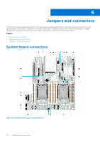
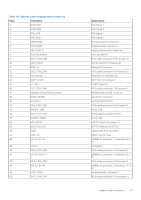
Table 44. System board jumpers and connectors Item Connector 1. FAN_SIG1 2. FAN_SIG2 3. PIB_SIG1 4. PIB_SIG2 5. INTRUSION 6. SYS_PWR1 7. SIG_PWR_0 8. Coin cell battery 9. SL6_CPU2_PB3 10. X16 (CPU2) 11. SYS_ID 12. SL5_CPU2_PA3 13. x16 (CPU2) 14. OCP 3.0 x16 15. J_TPM 16. SL7_CPU1_PA4 17. IDSDM/Internal USB connector 18. REAR_SERIAL 19. x4 (PCH) 20. SL8_CPU1_PB4 21. FRONT_USB 22. SL10_PCH_PA5 23. FRONT_VIDEO 24. x16 (CPU1) 25. SL9_PCH_SA1 26. ODD 27. RGT_CP 28. A3, A7, A1, A5 29. CPU 1 30. SL4_CPU1_PA2 31. A6, A2, A8, A4 32. SL3_CPU1_PB2 33. B3, B7, B1, B5 34. SYS_PWR2 35. SL2_CPU2_PA1 Description Fan Signal 1 Fan Signal 2 PIB Signal 1 PIB Signal 2 Intrusion Switch Connector System Power Connector 1 Power connector for cable riser Coin cell battery PCIe cable connector 6 (Processor 2) x16 PCIe slot 6 ( Processor 2) System ID Connector PCIe cable connector 5 (Processor 2) PCIe slot 5 ( Processor 2) OCP NIC 3.0 Connector TPM Connector PCIe cable connector 7 (Processor 1) IDSDM/Internal USB connector Serial Port Connector x4 PCIe slot 2 (PCH) PCIe cable connector 8 (Processor 1) Front USB BOSS signal connector (PCH) Front VGA x16 PCIe slot 1 (Processor 1) SATA Connector S9 (PCH) Optical disk drive connector Right Control Panel DIMMs for processor 1 Channels A, B, C, D Processor 1 PCIe cable connector 4 (Processor 1) DIMMs for processor 1 Channels A, B, C, D PCIe cable connector 3 (Processor 1) DIMMs for processor 2 Channels E, F, G, H System Power Connector 2 PCIe cable connector 2 (Processor 2) Jumpers and connectors 171
-
 1
1 -
2
-
3
-
4
-
5
-
6
-
7
-
8
-
9
-
10
-
11
-
12
-
13
-
14
-
15
-
16
-
17
-
18
-
19
-
20
-
21
-
22
-
23
-
24
-
25
-
26
-
27
-
28
-
29
-
30
-
31
-
32
-
33
-
34
-
35
-
36
-
37
-
38
-
39
-
40
-
41
-
42
-
43
-
44
-
45
-
46
-
47
-
48
-
49
-
50
-
51
-
52
-
53
-
54
-
55
-
56
-
57
-
58
-
59
-
60
-
61
-
62
-
63
-
64
-
65
-
66
-
67
-
68
-
69
-
70
-
71
-
72
-
73
-
74
-
75
-
76
-
77
-
78
-
79
-
80
-
81
-
82
-
83
-
84
-
85
-
86
-
87
-
88
-
89
-
90
-
91
-
92
-
93
-
94
-
95
-
96
-
97
-
98
-
99
-
100
-
101
-
102
-
103
-
104
-
105
-
106
-
107
-
108
-
109
-
110
-
111
-
112
-
113
-
114
-
115
-
116
-
117
-
118
-
119
-
120
-
121
-
122
-
123
-
124
-
125
-
126
-
127
-
128
-
129
-
130
-
131
-
132
-
133
-
134
-
135
-
136
-
137
-
138
-
139
-
140
-
141
-
142
-
143
-
144
-
145
-
146
-
147
-
148
-
149
-
150
-
151
-
152
-
153
-
154
-
155
-
156
-
157
-
158
-
159
-
160
-
161
-
162
-
163
-
164
-
165
-
 166
166 -
 167
167 -
 168
168 -
 169
169 -
 170
170 -
 171
171 -
 172
172 -
 173
173 -
 174
174 -
 175
175 -
 176
176 -
177
-
178
-
179
-
180
-
181
-
182
-
183
-
184
-
185
-
186
-
187
 |
 |
