Dell PowerEdge T550 EMC Installation and Service Manual - Page 151
Optional serial COM port, Removing the serial COM port
 |
View all Dell PowerEdge T550 manuals
Add to My Manuals
Save this manual to your list of manuals |
Page 151 highlights
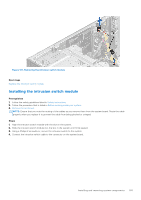
6. Align the OCP air shroud to the guide pins on the chassis and lower the OCP air shroud. Figure 156. Installing the OCP air shroud. Next steps 1. Install the air shroud. 2. Follow the procedure listed in After working inside your system. Optional serial COM port This is a service technician replaceable part only. Removing the serial COM port Prerequisites 1. Follow the safety guidelines listed in Safety instructions. 2. Follow the procedure that is listed in Before working inside your system. 3. Remove the air shroud. 4. Disconnect the cable connected to the serial COM port. Steps 1. Open the blue latch and slide the serial COM port out of the system. Installing and removing system components 151
-
 1
1 -
2
-
3
-
4
-
5
-
6
-
7
-
8
-
9
-
10
-
11
-
12
-
13
-
14
-
15
-
16
-
17
-
18
-
19
-
20
-
21
-
22
-
23
-
24
-
25
-
26
-
27
-
28
-
29
-
30
-
31
-
32
-
33
-
34
-
35
-
36
-
37
-
38
-
39
-
40
-
41
-
42
-
43
-
44
-
45
-
46
-
47
-
48
-
49
-
50
-
51
-
52
-
53
-
54
-
55
-
56
-
57
-
58
-
59
-
60
-
61
-
62
-
63
-
64
-
65
-
66
-
67
-
68
-
69
-
70
-
71
-
72
-
73
-
74
-
75
-
76
-
77
-
78
-
79
-
80
-
81
-
82
-
83
-
84
-
85
-
86
-
87
-
88
-
89
-
90
-
91
-
92
-
93
-
94
-
95
-
96
-
97
-
98
-
99
-
100
-
101
-
102
-
103
-
104
-
105
-
106
-
107
-
108
-
109
-
110
-
111
-
112
-
113
-
114
-
115
-
116
-
117
-
118
-
119
-
120
-
121
-
122
-
123
-
124
-
125
-
126
-
127
-
128
-
129
-
130
-
131
-
132
-
133
-
134
-
135
-
136
-
137
-
138
-
139
-
140
-
141
-
142
-
143
-
144
-
145
-
 146
146 -
 147
147 -
 148
148 -
 149
149 -
 150
150 -
 151
151 -
 152
152 -
 153
153 -
 154
154 -
 155
155 -
 156
156 -
157
-
158
-
159
-
160
-
161
-
162
-
163
-
164
-
165
-
166
-
167
-
168
-
169
-
170
-
171
-
172
-
173
-
174
-
175
-
176
-
177
-
178
-
179
-
180
-
181
-
182
-
183
-
184
-
185
-
186
-
187
 |
 |

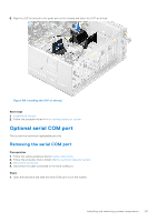
6.
Align the OCP air shroud to the guide pins on the chassis and lower the OCP air shroud.
Figure 156. Installing the OCP air shroud.
Next steps
1.
Install the air shroud
.
2.
Follow the procedure listed in
After working inside your system
.
Optional serial COM port
This is a service technician replaceable part only.
Removing the serial COM port
Prerequisites
1.
Follow the safety guidelines listed in
Safety instructions
.
2.
Follow the procedure that is listed in
Before working inside your system
.
3.
Remove the air shroud
.
4.
Disconnect the cable connected to the serial COM port.
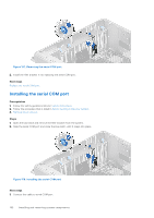
Steps
1.
Open the blue latch and slide the serial COM port out of the system.
Installing and removing system components
151