Dell PowerEdge T550 EMC Installation and Service Manual - Page 166
Next steps
 |
View all Dell PowerEdge T550 manuals
Add to My Manuals
Save this manual to your list of manuals |
Page 166 highlights
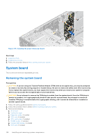
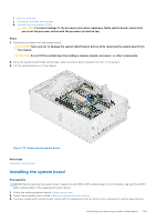
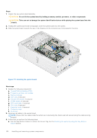
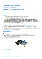
Steps 1. Unpack the new system board assembly. CAUTION: Do not lift the system board by holding a memory module, processor, or other components. CAUTION: Take care not to damage the system identification button while placing the system board into the chassis. 2. Holding the system board holder and plunger, lower the system board into the system. 3. Slide the system board towards the rear of the chassis until the connectors are firmly seated in the slots. Figure 177. Installing the system board Next steps 1. Replace the following components: a. Trusted Platform Module (TPM) b. Processors and heat sink modules c. Memory modules d. OCP card, if removed e. Internal USB module, if removed f. IDSDM module, if removed g. GPU card holder, if removed h. GPU card, if removed i. Expansion cards, if removed j. Cooling fan cage k. Air shroud 2. Reconnect all cables to the system board. NOTE: Ensure that the cables inside the system are routed along the chassis wall and secured using the cable securing bracket. 3. Ensure that you perform the following steps: a. Use the Easy Restore feature to restore the Service Tag. See the Restoring the system by using the Easy Restore feature section. 166 Installing and removing system components
-
 1
1 -
2
-
3
-
4
-
5
-
6
-
7
-
8
-
9
-
10
-
11
-
12
-
13
-
14
-
15
-
16
-
17
-
18
-
19
-
20
-
21
-
22
-
23
-
24
-
25
-
26
-
27
-
28
-
29
-
30
-
31
-
32
-
33
-
34
-
35
-
36
-
37
-
38
-
39
-
40
-
41
-
42
-
43
-
44
-
45
-
46
-
47
-
48
-
49
-
50
-
51
-
52
-
53
-
54
-
55
-
56
-
57
-
58
-
59
-
60
-
61
-
62
-
63
-
64
-
65
-
66
-
67
-
68
-
69
-
70
-
71
-
72
-
73
-
74
-
75
-
76
-
77
-
78
-
79
-
80
-
81
-
82
-
83
-
84
-
85
-
86
-
87
-
88
-
89
-
90
-
91
-
92
-
93
-
94
-
95
-
96
-
97
-
98
-
99
-
100
-
101
-
102
-
103
-
104
-
105
-
106
-
107
-
108
-
109
-
110
-
111
-
112
-
113
-
114
-
115
-
116
-
117
-
118
-
119
-
120
-
121
-
122
-
123
-
124
-
125
-
126
-
127
-
128
-
129
-
130
-
131
-
132
-
133
-
134
-
135
-
136
-
137
-
138
-
139
-
140
-
141
-
142
-
143
-
144
-
145
-
146
-
147
-
148
-
149
-
150
-
151
-
152
-
153
-
154
-
155
-
156
-
157
-
158
-
159
-
160
-
 161
161 -
 162
162 -
 163
163 -
 164
164 -
 165
165 -
 166
166 -
 167
167 -
 168
168 -
 169
169 -
 170
170 -
 171
171 -
172
-
173
-
174
-
175
-
176
-
177
-
178
-
179
-
180
-
181
-
182
-
183
-
184
-
185
-
186
-
187
 |
 |
