Dell Precision 610 Dell Precision WorkStation 610 Mini Tower Systems User's Gu - Page 111
Installing System Board Options, DIMM sockets, DIMMs 4
 |
View all Dell Precision 610 manuals
Add to My Manuals
Save this manual to your list of manuals |
Page 111 highlights
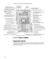
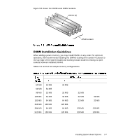
Figure 9-5 shows the DIMMs and DIMM sockets. DIMMs (4) A CB D DIMM sockets When adding system memory, you may install DIMMs in any order. For optimum operation, Dell recommends installing the DIMMs starting with socket A (closest to the top edge of the system board) and working toward socket D, leaving no open sockets between installed DIMMs. Tables 9-1 and 9-2 list sample memory configurations. 64 MB 64 MB 96 MB 128 MB 192 MB 256 MB 384 MB 512 MB 32 MB 64 MB 32 MB 32 MB 64 MB 128 MB 64 MB 128 MB 32 MB 32 MB 32 MB 64 MB 128 MB 64 MB 128 MB 32 MB 32 MB 32 MB 128 MB 128 MB 32 MB 32 MB 128 MB 128 MB Installing System Board Options 9-7
-
 1
1 -
2
-
3
-
4
-
5
-
6
-
7
-
8
-
9
-
10
-
11
-
12
-
13
-
14
-
15
-
16
-
17
-
18
-
19
-
20
-
21
-
22
-
23
-
24
-
25
-
26
-
27
-
28
-
29
-
30
-
31
-
32
-
33
-
34
-
35
-
36
-
37
-
38
-
39
-
40
-
41
-
42
-
43
-
44
-
45
-
46
-
47
-
48
-
49
-
50
-
51
-
52
-
53
-
54
-
55
-
56
-
57
-
58
-
59
-
60
-
61
-
62
-
63
-
64
-
65
-
66
-
67
-
68
-
69
-
70
-
71
-
72
-
73
-
74
-
75
-
76
-
77
-
78
-
79
-
80
-
81
-
82
-
83
-
84
-
85
-
86
-
87
-
88
-
89
-
90
-
91
-
92
-
93
-
94
-
95
-
96
-
97
-
98
-
99
-
100
-
101
-
102
-
103
-
104
-
105
-
 106
106 -
 107
107 -
 108
108 -
 109
109 -
 110
110 -
 111
111 -
 112
112 -
 113
113 -
 114
114 -
 115
115 -
 116
116 -
117
-
118
-
119
-
120
-
121
-
122
-
123
-
124
-
125
-
126
-
127
-
128
-
129
-
130
-
131
-
132
-
133
-
134
-
135
-
136
-
137
-
138
-
139
-
140
-
141
-
142
-
143
-
144
-
145
-
146
-
147
-
148
-
149
-
150
-
151
-
152
-
153
-
154
-
155
-
156
-
157
-
158
-
159
-
160
-
161
-
162
-
163
-
164
-
165
-
166
-
167
-
168
-
169
-
170
-
171
-
172
-
173
-
174
-
175
-
176
-
177
-
178
-
179
-
180
-
181
-
182
-
183
-
184
-
185
-
186
-
187
-
188
-
189
-
190
-
191
-
192
-
193
-
194
-
195
-
196
-
197
-
198
-
199
-
200
-
201
-
202
-
203
-
204
-
205
-
206
-
207
-
208
-
209
-
210
-
211
-
212
-
213
-
214
-
215
-
216
-
217
-
218
-
219
-
220
-
221
-
222
-
223
-
224
-
225
-
226
-
227
-
228
-
229
-
230
 |
 |

Installing System Board Options
9-7
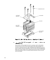
Figure 9-5 shows the DIMMs and DIMM sockets.
’,00±,QVWDOODWLRQ±*XLGHOLQHV
When adding system memory, you may install DIMMs in any order. For optimum
operation, Dell recommends installing the DIMMs starting with socket A (closest to
the top edge of the system board) and working toward socket D, leaving no open
sockets between installed DIMMs.
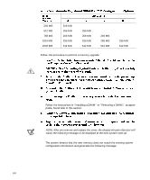
Tables 9-1 and 9-2 list sample memory configurations.
64 MB
32 MB
32 MB
64 MB
64 MB
96 MB
32 MB
32 MB
32 MB
128 MB
32 MB
32 MB
32 MB
32 MB
192 MB
64 MB
64 MB
32 MB
32 MB
256 MB
128 MB
128 MB
384 MB
64 MB
64 MB
128 MB
128 MB
512 MB
128 MB
128 MB
128 MB
128 MB
A
B
DIMM sockets
DIMMs (4)
C
D