Dell Precision 610 Dell Precision WorkStation 610 Mini Tower Systems User's Gu - Page 131
Installing Drives
 |
View all Dell Precision 610 manuals
Add to My Manuals
Save this manual to your list of manuals |
Page 131 highlights
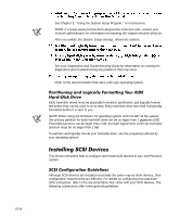
This section includes information on installing, partitioning, and formatting EIDE harddisk drives. For instructions on installing, partitioning, and formatting SCSI hard-disk drives, see "Installing SCSI Devices" found later in this chapter. Up to four 1-inch or up to two 1-inch and two 1.6-inch EIDE drives can be installed in the internal hard-disk drive cage below the externally accessible 5.25-inch drive bays. All EIDE devices should be configured for the cable select jumper position, which assigns master and slave status to devices by their position on the EIDE cable. When two EIDE devices are connected to a single EIDE cable and are configured for the cable select jumper position, the device attached to the last connector on the interface cable is the master or boot device (drive 0) and the device attached to the middle connector on the interface cable is the slave device (drive 1). Refer to the drive documentation in your upgrade kit for information on setting devices to the cable select jumper position. With the two EIDE interface connectors on the system board, your system can support up to four EIDE devices. EIDE hard-disk drives should be connected to the EIDE interface connector labeled "IDE1." (EIDE tape drives and CD-ROM drives should be connected to the EIDE interface connector labeled "IDE2.") Install an EIDE hard-disk drive in the hard-disk drive bracket as follows: Check the documentation that accompanied the drive to verify that it is configured for your computer system. Installing Drives 10-11
-
 1
1 -
2
-
3
-
4
-
5
-
6
-
7
-
8
-
9
-
10
-
11
-
12
-
13
-
14
-
15
-
16
-
17
-
18
-
19
-
20
-
21
-
22
-
23
-
24
-
25
-
26
-
27
-
28
-
29
-
30
-
31
-
32
-
33
-
34
-
35
-
36
-
37
-
38
-
39
-
40
-
41
-
42
-
43
-
44
-
45
-
46
-
47
-
48
-
49
-
50
-
51
-
52
-
53
-
54
-
55
-
56
-
57
-
58
-
59
-
60
-
61
-
62
-
63
-
64
-
65
-
66
-
67
-
68
-
69
-
70
-
71
-
72
-
73
-
74
-
75
-
76
-
77
-
78
-
79
-
80
-
81
-
82
-
83
-
84
-
85
-
86
-
87
-
88
-
89
-
90
-
91
-
92
-
93
-
94
-
95
-
96
-
97
-
98
-
99
-
100
-
101
-
102
-
103
-
104
-
105
-
106
-
107
-
108
-
109
-
110
-
111
-
112
-
113
-
114
-
115
-
116
-
117
-
118
-
119
-
120
-
121
-
122
-
123
-
124
-
125
-
 126
126 -
 127
127 -
 128
128 -
 129
129 -
 130
130 -
 131
131 -
 132
132 -
 133
133 -
 134
134 -
 135
135 -
 136
136 -
137
-
138
-
139
-
140
-
141
-
142
-
143
-
144
-
145
-
146
-
147
-
148
-
149
-
150
-
151
-
152
-
153
-
154
-
155
-
156
-
157
-
158
-
159
-
160
-
161
-
162
-
163
-
164
-
165
-
166
-
167
-
168
-
169
-
170
-
171
-
172
-
173
-
174
-
175
-
176
-
177
-
178
-
179
-
180
-
181
-
182
-
183
-
184
-
185
-
186
-
187
-
188
-
189
-
190
-
191
-
192
-
193
-
194
-
195
-
196
-
197
-
198
-
199
-
200
-
201
-
202
-
203
-
204
-
205
-
206
-
207
-
208
-
209
-
210
-
211
-
212
-
213
-
214
-
215
-
216
-
217
-
218
-
219
-
220
-
221
-
222
-
223
-
224
-
225
-
226
-
227
-
228
-
229
-
230
 |
 |
