Dell Precision 610 Dell Precision WorkStation 610 Mini Tower Systems User's Gu - Page 21
Deohv
 |
View all Dell Precision 610 manuals
Add to My Manuals
Save this manual to your list of manuals |
Page 21 highlights
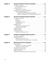
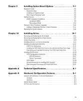
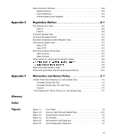
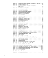
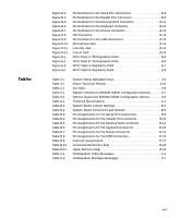
Figure B-3. Figure B-4. Figure B-5. Figure B-6. Figure B-7. Figure B-8. Figure B-9. Figure B-10. Figure B-11. Figure B-12. Figure E-1. Figure E-2. Figure E-3. Figure E-4. Pin Numbers for the Serial Port Connectors B-8 Pin Numbers for the Parallel Port Connector B-9 Pin Numbers for the External SCSI Connector B-11 Pin Numbers for the Keyboard Connector B-13 Pin Numbers for the Mouse Connector B-14 NIC Connector B-14 Pin Numbers for the USB Connectors B-15 Microphone Jack B-16 Line-Out Jack B-16 Line-In Jack B-16 VCCI Class A ITE Regulatory Mark E-6 VCCI Class B ITE Regulatory Mark E-6 MOC Class A Regulatory Mark E-7 MOC Class B Regulatory Mark E-8 Table 3-1. Table 3-2. Table 4-1. Table 9-1. Table 9-2. Table A-1. Table B-1. Table B-2. Table B-3. Table B-4. Table B-5. Table B-6. Table B-7. Table B-8. Table B-9. Table B-10. Table B-11. Table C-1. Table C-2. System-Setup Navigation Keys 3-3 Power Time-Out Periods 3-16 ICU Keys 4-6 Sample Unbuffered SDRAM DIMM Configuration Options 9-7 Sample Registered SDRAM DIMM Configuration Options 9-8 Technical Specifications A-1 System-Board Jumper Settings B-4 System Board Connectors and Sockets B-5 Pin Assignments for the Serial Port Connectors B-9 Pin Assignments for the Parallel Port Connector B-10 Pin Assignments for the External SCSI Connector B-11 Pin Assignments for the Keyboard Connector B-13 Pin Assignments for the Mouse Connector B-14 Pin Assignments for the USB Connectors B-15 Interrupt Assignments B-17 Conventional Memory Map B-18 Upper Memory Map B-19 Configuration Utility Messages C-1 Configuration Manager Messages C-7 xxiii
-
 1
1 -
2
-
3
-
4
-
5
-
6
-
7
-
8
-
9
-
10
-
11
-
12
-
13
-
14
-
15
-
 16
16 -
 17
17 -
 18
18 -
 19
19 -
 20
20 -
 21
21 -
 22
22 -
 23
23 -
 24
24 -
 25
25 -
 26
26 -
27
-
28
-
29
-
30
-
31
-
32
-
33
-
34
-
35
-
36
-
37
-
38
-
39
-
40
-
41
-
42
-
43
-
44
-
45
-
46
-
47
-
48
-
49
-
50
-
51
-
52
-
53
-
54
-
55
-
56
-
57
-
58
-
59
-
60
-
61
-
62
-
63
-
64
-
65
-
66
-
67
-
68
-
69
-
70
-
71
-
72
-
73
-
74
-
75
-
76
-
77
-
78
-
79
-
80
-
81
-
82
-
83
-
84
-
85
-
86
-
87
-
88
-
89
-
90
-
91
-
92
-
93
-
94
-
95
-
96
-
97
-
98
-
99
-
100
-
101
-
102
-
103
-
104
-
105
-
106
-
107
-
108
-
109
-
110
-
111
-
112
-
113
-
114
-
115
-
116
-
117
-
118
-
119
-
120
-
121
-
122
-
123
-
124
-
125
-
126
-
127
-
128
-
129
-
130
-
131
-
132
-
133
-
134
-
135
-
136
-
137
-
138
-
139
-
140
-
141
-
142
-
143
-
144
-
145
-
146
-
147
-
148
-
149
-
150
-
151
-
152
-
153
-
154
-
155
-
156
-
157
-
158
-
159
-
160
-
161
-
162
-
163
-
164
-
165
-
166
-
167
-
168
-
169
-
170
-
171
-
172
-
173
-
174
-
175
-
176
-
177
-
178
-
179
-
180
-
181
-
182
-
183
-
184
-
185
-
186
-
187
-
188
-
189
-
190
-
191
-
192
-
193
-
194
-
195
-
196
-
197
-
198
-
199
-
200
-
201
-
202
-
203
-
204
-
205
-
206
-
207
-
208
-
209
-
210
-
211
-
212
-
213
-
214
-
215
-
216
-
217
-
218
-
219
-
220
-
221
-
222
-
223
-
224
-
225
-
226
-
227
-
228
-
229
-
230
 |
 |
