Dell Precision 610 Dell Precision WorkStation 610 Mini Tower Systems User's Gu - Page 125
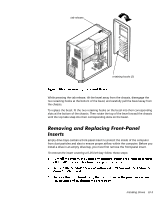
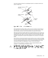
pin on one connector matches a tab or a filled-in hole on the other connector see Fig
 |
View all Dell Precision 610 manuals
Add to My Manuals
Save this manual to your list of manuals |
Page 125 highlights
The drive's interface connector is a card-edge connector or a header connector, as shown in Figure 10-5. card-edge connector notch on drive header connector colored on drive strip colored strip interface cables When attaching the interface cable to a drive, be sure to match the colored strip on the cable to pin 1 of the drive's interface connector. For the location of pin 1 on the drive's interface connector, see the documentation that came with the drive. When disconnecting an interface cable from the system board, be sure to press in on the locking tabs on the cable connector (if any) before disconnecting the cable. When attaching an interface cable to the system board, be sure that the locking tabs snap into place, ensuring that the cable is firmly attached to the connector on the system board. Most interface connectors are keyed for correct insertion; that is, a notch or a missing pin on one connector matches a tab or a filled-in hole on the other connector (see Figure 10-5). Keying ensures that the pin-1 wire in the cable (indicated by the colored strip along one edge of the cable) goes to the pin-1 end of the connector. The pin-1 end of a connector on a board or a card is usually indicated by a silkscreened "1" printed directly on the board or card. Installing Drives 10-5
-
 1
1 -
2
-
3
-
4
-
5
-
6
-
7
-
8
-
9
-
10
-
11
-
12
-
13
-
14
-
15
-
16
-
17
-
18
-
19
-
20
-
21
-
22
-
23
-
24
-
25
-
26
-
27
-
28
-
29
-
30
-
31
-
32
-
33
-
34
-
35
-
36
-
37
-
38
-
39
-
40
-
41
-
42
-
43
-
44
-
45
-
46
-
47
-
48
-
49
-
50
-
51
-
52
-
53
-
54
-
55
-
56
-
57
-
58
-
59
-
60
-
61
-
62
-
63
-
64
-
65
-
66
-
67
-
68
-
69
-
70
-
71
-
72
-
73
-
74
-
75
-
76
-
77
-
78
-
79
-
80
-
81
-
82
-
83
-
84
-
85
-
86
-
87
-
88
-
89
-
90
-
91
-
92
-
93
-
94
-
95
-
96
-
97
-
98
-
99
-
100
-
101
-
102
-
103
-
104
-
105
-
106
-
107
-
108
-
109
-
110
-
111
-
112
-
113
-
114
-
115
-
116
-
117
-
118
-
119
-
 120
120 -
 121
121 -
 122
122 -
 123
123 -
 124
124 -
 125
125 -
 126
126 -
 127
127 -
 128
128 -
 129
129 -
 130
130 -
131
-
132
-
133
-
134
-
135
-
136
-
137
-
138
-
139
-
140
-
141
-
142
-
143
-
144
-
145
-
146
-
147
-
148
-
149
-
150
-
151
-
152
-
153
-
154
-
155
-
156
-
157
-
158
-
159
-
160
-
161
-
162
-
163
-
164
-
165
-
166
-
167
-
168
-
169
-
170
-
171
-
172
-
173
-
174
-
175
-
176
-
177
-
178
-
179
-
180
-
181
-
182
-
183
-
184
-
185
-
186
-
187
-
188
-
189
-
190
-
191
-
192
-
193
-
194
-
195
-
196
-
197
-
198
-
199
-
200
-
201
-
202
-
203
-
204
-
205
-
206
-
207
-
208
-
209
-
210
-
211
-
212
-
213
-
214
-
215
-
216
-
217
-
218
-
219
-
220
-
221
-
222
-
223
-
224
-
225
-
226
-
227
-
228
-
229
-
230
 |
 |
