HP BladeSystem bc2800 HP BladeSystem PC Blade Enclosure Integrated Administrat - Page 30
Web Browser Interface, Enclosure Information Field Descriptions - Status Area continued
 |
View all HP BladeSystem bc2800 manuals
Add to My Manuals
Save this manual to your list of manuals |
Page 30 highlights
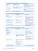
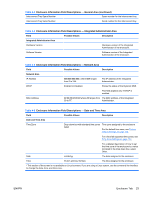
Table 4-1 Enclosure Information Field Descriptions - Status Area (continued) Enclosure Status OK, Degraded, or Failed. Status of the enclosure. Fan Status Redundant or non-redundant. Redundant: all fans are functional. Nonredundant: at least one fan is not functional. Fan #1 - Fan #4 OK, Standby, Degraded, Failed, or Testing. Percentage of full fan speed. Status of fans 1 through 4. Fan Spare Number The spare number for the fans installed in the enclosure. Temperature OK, Warm, Caution, or Critical. Enclosure component temperature sensor. Table 4-2 Enclosure Information Field Descriptions - Power Area Field Possible Values Power Area Power Subsystem Status Redundant or Non-redundant. Total Capacity Power Supply #1 and #2 Status AC Input #1 and #2 Status Power Supply Spare Number Watts. OK, Degraded, or Failed. OK, Degraded, or Failed. Description Redundant: both power supplies are functional. Non-redundant: one power supply is not functional. Total capacity of the power supplies. Status of power supply #1 and power supply #2. Status of AC input to power supply #1 and AC input to power supply #2. The spare number for the power supplies installed in the enclosure. Table 4-3 Enclosure Information Field Descriptions - General Area Field Possible Values Description General Area Enclosure Type Enclosure product type. Option Part Number Part number for the enclosure. Serial Number Serial number for the enclosure. Asset Tag Maximum 31 characters including all alphanumeric, dash, and underscore characters Asset tag Only enclosure administrators have write access to this field. For the default asset tag value, see Factory Default Settings on page 128. Interconnect Tray Type HP PC Blade Enclosure Interconnect Switch Type of interconnect tray. HP PC Blade Enclosure RJ-21 Interconnect Switch HP PC Blade Enclosure RJ-45 Interconnect Switch Interconnect Tray Part Number Part number for the interconnect tray. 22 Chapter 4 Web Browser Interface ENWW
-
 1
1 -
2
-
3
-
4
-
5
-
6
-
7
-
8
-
9
-
10
-
11
-
12
-
13
-
14
-
15
-
16
-
17
-
18
-
19
-
20
-
21
-
22
-
23
-
24
-
 25
25 -
 26
26 -
 27
27 -
 28
28 -
 29
29 -
 30
30 -
 31
31 -
 32
32 -
 33
33 -
 34
34 -
 35
35 -
36
-
37
-
38
-
39
-
40
-
41
-
42
-
43
-
44
-
45
-
46
-
47
-
48
-
49
-
50
-
51
-
52
-
53
-
54
-
55
-
56
-
57
-
58
-
59
-
60
-
61
-
62
-
63
-
64
-
65
-
66
-
67
-
68
-
69
-
70
-
71
-
72
-
73
-
74
-
75
-
76
-
77
-
78
-
79
-
80
-
81
-
82
-
83
-
84
-
85
-
86
-
87
-
88
-
89
-
90
-
91
-
92
-
93
-
94
-
95
-
96
-
97
-
98
-
99
-
100
-
101
-
102
-
103
-
104
-
105
-
106
-
107
-
108
-
109
-
110
-
111
-
112
-
113
-
114
-
115
-
116
-
117
-
118
-
119
-
120
-
121
-
122
-
123
-
124
-
125
-
126
-
127
-
128
-
129
-
130
-
131
-
132
-
133
-
134
-
135
-
136
-
137
-
138
-
139
-
140
-
141
-
142
-
143
-
144
-
145
-
146
-
147
 |
 |
