HP Dc5800 Service Reference Guide: HP Compaq dc5800 Business PC - Page 102
ReadyBoost Card
 |
UPC - 883585860944
View all HP Dc5800 manuals
Add to My Manuals
Save this manual to your list of manuals |
Page 102 highlights
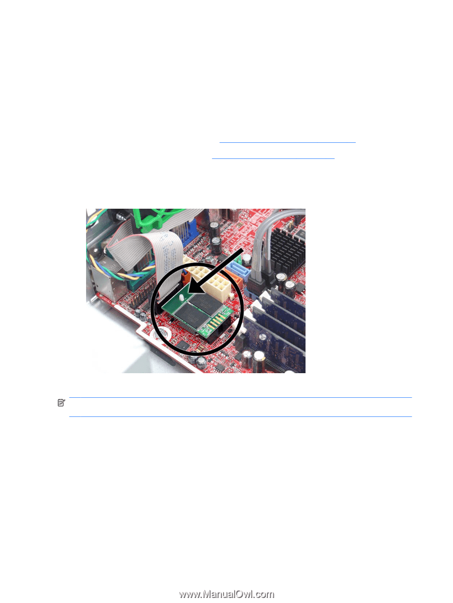
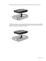
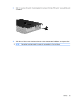
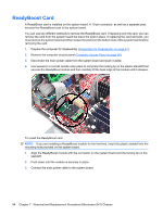
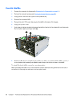
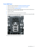
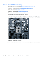
ReadyBoost Card A ReadyBoost card is installed on the system board. A 10-pin connector, as well as a separate post, secures the ReadyBoost card to the system board. You can use two different methods to remove the ReadyBoost card. If replacing only the card, you can remove the card from the system board but leave the post in place. If replacing the card and post, you must remove the system board and then loosen the post from the bottom side of the system board before removing the card. 1. Prepare the computer for disassembly (Preparation for Disassembly on page 61). 2. Remove the computer access panel (Computer Access Panel on page 66). 3. Disconnect the main power cable from the system board and push it aside. 4. Use tweezers or a small needle-nose pliers to compress the locking tip on the plastic standoff that secures the ReadyBoost module and then carefully lift the back edge of the module until it releases. To install the ReadyBoost card: NOTE: If you are installing a ReadyBoost module for the first time, insert the plastic standoff into the mounting hole provided on the system board. 1. Align the ReadyBoost module with the connector on the system board and the locking tip on the standoff. 2. Push down until the module is securely in place. 3. Connect the main power cable to the system board. 94 Chapter 7 Removal and Replacement Procedures Microtower (MT) Chassis
-
 1
1 -
2
-
3
-
4
-
5
-
6
-
7
-
8
-
9
-
10
-
11
-
12
-
13
-
14
-
15
-
16
-
17
-
18
-
19
-
20
-
21
-
22
-
23
-
24
-
25
-
26
-
27
-
28
-
29
-
30
-
31
-
32
-
33
-
34
-
35
-
36
-
37
-
38
-
39
-
40
-
41
-
42
-
43
-
44
-
45
-
46
-
47
-
48
-
49
-
50
-
51
-
52
-
53
-
54
-
55
-
56
-
57
-
58
-
59
-
60
-
61
-
62
-
63
-
64
-
65
-
66
-
67
-
68
-
69
-
70
-
71
-
72
-
73
-
74
-
75
-
76
-
77
-
78
-
79
-
80
-
81
-
82
-
83
-
84
-
85
-
86
-
87
-
88
-
89
-
90
-
91
-
92
-
93
-
94
-
95
-
96
-
 97
97 -
 98
98 -
 99
99 -
 100
100 -
 101
101 -
 102
102 -
 103
103 -
 104
104 -
 105
105 -
 106
106 -
 107
107 -
108
-
109
-
110
-
111
-
112
-
113
-
114
-
115
-
116
-
117
-
118
-
119
-
120
-
121
-
122
-
123
-
124
-
125
-
126
-
127
-
128
-
129
-
130
-
131
-
132
-
133
-
134
-
135
-
136
-
137
-
138
-
139
-
140
-
141
-
142
-
143
-
144
-
145
-
146
-
147
-
148
-
149
-
150
-
151
-
152
-
153
-
154
-
155
-
156
-
157
-
158
-
159
-
160
-
161
-
162
-
163
-
164
-
165
-
166
-
167
-
168
-
169
-
170
-
171
-
172
-
173
-
174
-
175
-
176
-
177
-
178
-
179
-
180
-
181
-
182
-
183
-
184
-
185
-
186
-
187
-
188
-
189
-
190
-
191
-
192
-
193
-
194
-
195
-
196
-
197
-
198
-
199
-
200
-
201
-
202
-
203
-
204
-
205
-
206
-
207
-
208
-
209
-
210
-
211
-
212
-
213
-
214
-
215
-
216
-
217
-
218
-
219
-
220
-
221
-
222
-
223
-
224
-
225
-
226
-
227
-
228
-
229
-
230
-
231
-
232
-
233
-
234
-
235
-
236
-
237
-
238
-
239
-
240
-
241
-
242
-
243
-
244
-
245
-
246
-
247
-
248
-
249
-
250
-
251
-
252
-
253
-
254
-
255
 |
 |