HP Dc5800 Service Reference Guide: HP Compaq dc5800 Business PC - Page 79
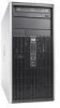
CAUTION, WARNING, Electrostatic Discharge Information, on Preparation for Disassembly
 |
UPC - 883585860944
View all HP Dc5800 manuals
Add to My Manuals
Save this manual to your list of manuals |
Page 79 highlights
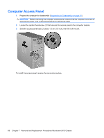
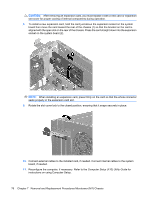
Item Description 1 DIMM socket XMM1, Channel A (populate first) 2 DIMM socket XMM2, Channel A 3 DIMM socket XMM3, Channel B (populate second) 4 DIMM socket XMM4, Channel B NOTE: A DIMM must occupy the XMM1 socket. Socket Color Black White Black White The system will automatically operate in single channel mode, dual channel mode, or flex mode, depending on how the DIMMs are installed. ● The system will operate in single channel mode if the DIMM sockets are populated in one channel only. ● The system will operate in a higher-performing dual channel mode if the total memory capacity of the DIMMs in Channel A is equal to the total memory capacity of the DIMMs in Channel B. The technology and device width can vary between the channels. For example, if Channel A is populated with two 512MB DIMMs and Channel B is populated with one 1GB DIMM, the system will operate in dual channel mode. ● The system will operate in flex mode if the total memory capacity of the DIMMs in Channel A is not equal to the total memory capacity of the DIMMs in Channel B. In flex mode, the channel populated with the least amount of memory describes the total amount of memory assigned to dual channel and the remainder is assigned to single channel. For optimal speed, the channels should be balanced so that the largest amount of memory is spread between the two channels. If one channel will have more memory than the other, the larger amount should be assigned to Channel A. For example, if you are populating the sockets with one 1GB DIMM, and three 512MB DIMMs, Channel A should be populated with the 1GB DIMM and one 512MB DIMM, and Channel B should be populated with the two 512MB DIMMs. With this configuration, 2GB will run as dual channel and 512MB will run as single channel. ● In any mode, the maximum operational speed is determined by the slowest DIMM in the system. CAUTION: The memory module sockets have gold metal contacts. When upgrading the memory, it is important to use memory modules with gold metal contacts to prevent corrosion and/or oxidation resulting from having incompatible metals in contact with each other. Static electricity can damage the electronic components of the computer or optional cards. Before beginning these procedures, ensure that you are discharged of static electricity by briefly touching a grounded metal object. Refer to Electrostatic Discharge Information on page 53 for more information. When handling a memory module, be careful not to touch any of the contacts. Doing so may damage the module. 1. Prepare the computer for disassembly (Preparation for Disassembly on page 61). 2. Remove the computer access panel (Computer Access Panel on page 66). WARNING! To reduce risk of personal injury from hot surfaces, allow the internal system components to cool before touching. Memory 71
-
 1
1 -
2
-
3
-
4
-
5
-
6
-
7
-
8
-
9
-
10
-
11
-
12
-
13
-
14
-
15
-
16
-
17
-
18
-
19
-
20
-
21
-
22
-
23
-
24
-
25
-
26
-
27
-
28
-
29
-
30
-
31
-
32
-
33
-
34
-
35
-
36
-
37
-
38
-
39
-
40
-
41
-
42
-
43
-
44
-
45
-
46
-
47
-
48
-
49
-
50
-
51
-
52
-
53
-
54
-
55
-
56
-
57
-
58
-
59
-
60
-
61
-
62
-
63
-
64
-
65
-
66
-
67
-
68
-
69
-
70
-
71
-
72
-
73
-
 74
74 -
 75
75 -
 76
76 -
 77
77 -
 78
78 -
 79
79 -
 80
80 -
 81
81 -
 82
82 -
 83
83 -
 84
84 -
85
-
86
-
87
-
88
-
89
-
90
-
91
-
92
-
93
-
94
-
95
-
96
-
97
-
98
-
99
-
100
-
101
-
102
-
103
-
104
-
105
-
106
-
107
-
108
-
109
-
110
-
111
-
112
-
113
-
114
-
115
-
116
-
117
-
118
-
119
-
120
-
121
-
122
-
123
-
124
-
125
-
126
-
127
-
128
-
129
-
130
-
131
-
132
-
133
-
134
-
135
-
136
-
137
-
138
-
139
-
140
-
141
-
142
-
143
-
144
-
145
-
146
-
147
-
148
-
149
-
150
-
151
-
152
-
153
-
154
-
155
-
156
-
157
-
158
-
159
-
160
-
161
-
162
-
163
-
164
-
165
-
166
-
167
-
168
-
169
-
170
-
171
-
172
-
173
-
174
-
175
-
176
-
177
-
178
-
179
-
180
-
181
-
182
-
183
-
184
-
185
-
186
-
187
-
188
-
189
-
190
-
191
-
192
-
193
-
194
-
195
-
196
-
197
-
198
-
199
-
200
-
201
-
202
-
203
-
204
-
205
-
206
-
207
-
208
-
209
-
210
-
211
-
212
-
213
-
214
-
215
-
216
-
217
-
218
-
219
-
220
-
221
-
222
-
223
-
224
-
225
-
226
-
227
-
228
-
229
-
230
-
231
-
232
-
233
-
234
-
235
-
236
-
237
-
238
-
239
-
240
-
241
-
242
-
243
-
244
-
245
-
246
-
247
-
248
-
249
-
250
-
251
-
252
-
253
-
254
-
255
 |
 |