HP Dc5800 Service Reference Guide: HP Compaq dc5800 Business PC - Page 150
Installing a Drive into the 3.5-inch External Drive Bay, Installing and Removing Drives, - sff power supply
 |
UPC - 883585860944
View all HP Dc5800 manuals
Add to My Manuals
Save this manual to your list of manuals |
Page 150 highlights
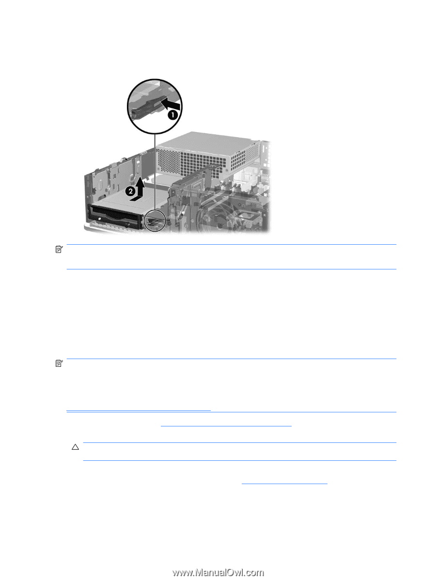
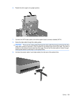
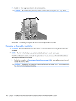
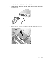
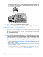
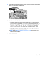
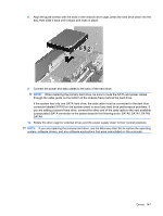
3. Press the green drive retainer latch (1) located on the right side of the drive to disengage the drive from the drive cage. While pressing the drive retainer latch, slide the drive back until it stops, then lift it up and out of the drive cage (2). NOTE: To replace the 3.5-inch drive, reverse the removal procedure. When replacing a 3.5-inch drive, transfer the four guide screws from the old drive to the new one. Installing a Drive into the 3.5-inch External Drive Bay Depending on the computer configuration, the 3.5-inch external drive bay on the front of the computer may be configured with a media card reader or a diskette drive, or it may be an empty drive bay. If the computer was not configured with a 3.5-inch drive, you can install a media card reader, diskette drive, or hard drive into the drive bay. The 3.5-inch bay is located underneath the optical drive. To install a drive into the 3.5-inch bay: NOTE: Install guide screws to ensure the drive will line up correctly in the drive cage and lock in place. HP has provided extra guide screws for the external drive bays (four 6-32 standard screws and four M3 metric screws), installed in the front of the chassis, under the front bezel. A secondary hard drive uses 6-32 standard screws. All other drives (except the primary hard drive) use M3 metric screws. The HPsupplied M3 metric screws are black and the HP-supplied 6-32 standard screws are silver. Refer to Installing and Removing Drives on page 133 for illustrations of the guide screw locations. 1. Follow the procedure in Removing an Optical Drive on page 136to remove the optical drive and access the 3.5-inch drive bay. CAUTION: Ensure that the computer is turned off and that the power cord is disconnected from the electrical outlet before proceeding. 2. If you are installing a diskette drive or media card reader in a bay covered by a bezel blank, remove the front bezel then remove the bezel blank. See Bezel Blanks on page 118 for more information. 142 Chapter 8 Removal and Replacement Procedures Small Form Factor (SFF) Chassis
-
 1
1 -
2
-
3
-
4
-
5
-
6
-
7
-
8
-
9
-
10
-
11
-
12
-
13
-
14
-
15
-
16
-
17
-
18
-
19
-
20
-
21
-
22
-
23
-
24
-
25
-
26
-
27
-
28
-
29
-
30
-
31
-
32
-
33
-
34
-
35
-
36
-
37
-
38
-
39
-
40
-
41
-
42
-
43
-
44
-
45
-
46
-
47
-
48
-
49
-
50
-
51
-
52
-
53
-
54
-
55
-
56
-
57
-
58
-
59
-
60
-
61
-
62
-
63
-
64
-
65
-
66
-
67
-
68
-
69
-
70
-
71
-
72
-
73
-
74
-
75
-
76
-
77
-
78
-
79
-
80
-
81
-
82
-
83
-
84
-
85
-
86
-
87
-
88
-
89
-
90
-
91
-
92
-
93
-
94
-
95
-
96
-
97
-
98
-
99
-
100
-
101
-
102
-
103
-
104
-
105
-
106
-
107
-
108
-
109
-
110
-
111
-
112
-
113
-
114
-
115
-
116
-
117
-
118
-
119
-
120
-
121
-
122
-
123
-
124
-
125
-
126
-
127
-
128
-
129
-
130
-
131
-
132
-
133
-
134
-
135
-
136
-
137
-
138
-
139
-
140
-
141
-
142
-
143
-
144
-
 145
145 -
 146
146 -
 147
147 -
 148
148 -
 149
149 -
 150
150 -
 151
151 -
 152
152 -
 153
153 -
 154
154 -
 155
155 -
156
-
157
-
158
-
159
-
160
-
161
-
162
-
163
-
164
-
165
-
166
-
167
-
168
-
169
-
170
-
171
-
172
-
173
-
174
-
175
-
176
-
177
-
178
-
179
-
180
-
181
-
182
-
183
-
184
-
185
-
186
-
187
-
188
-
189
-
190
-
191
-
192
-
193
-
194
-
195
-
196
-
197
-
198
-
199
-
200
-
201
-
202
-
203
-
204
-
205
-
206
-
207
-
208
-
209
-
210
-
211
-
212
-
213
-
214
-
215
-
216
-
217
-
218
-
219
-
220
-
221
-
222
-
223
-
224
-
225
-
226
-
227
-
228
-
229
-
230
-
231
-
232
-
233
-
234
-
235
-
236
-
237
-
238
-
239
-
240
-
241
-
242
-
243
-
244
-
245
-
246
-
247
-
248
-
249
-
250
-
251
-
252
-
253
-
254
-
255
 |
 |