HP Dc5800 Service Reference Guide: HP Compaq dc5800 Business PC - Page 164
Power Switch Assembly
 |
UPC - 883585860944
View all HP Dc5800 manuals
Add to My Manuals
Save this manual to your list of manuals |
Page 164 highlights
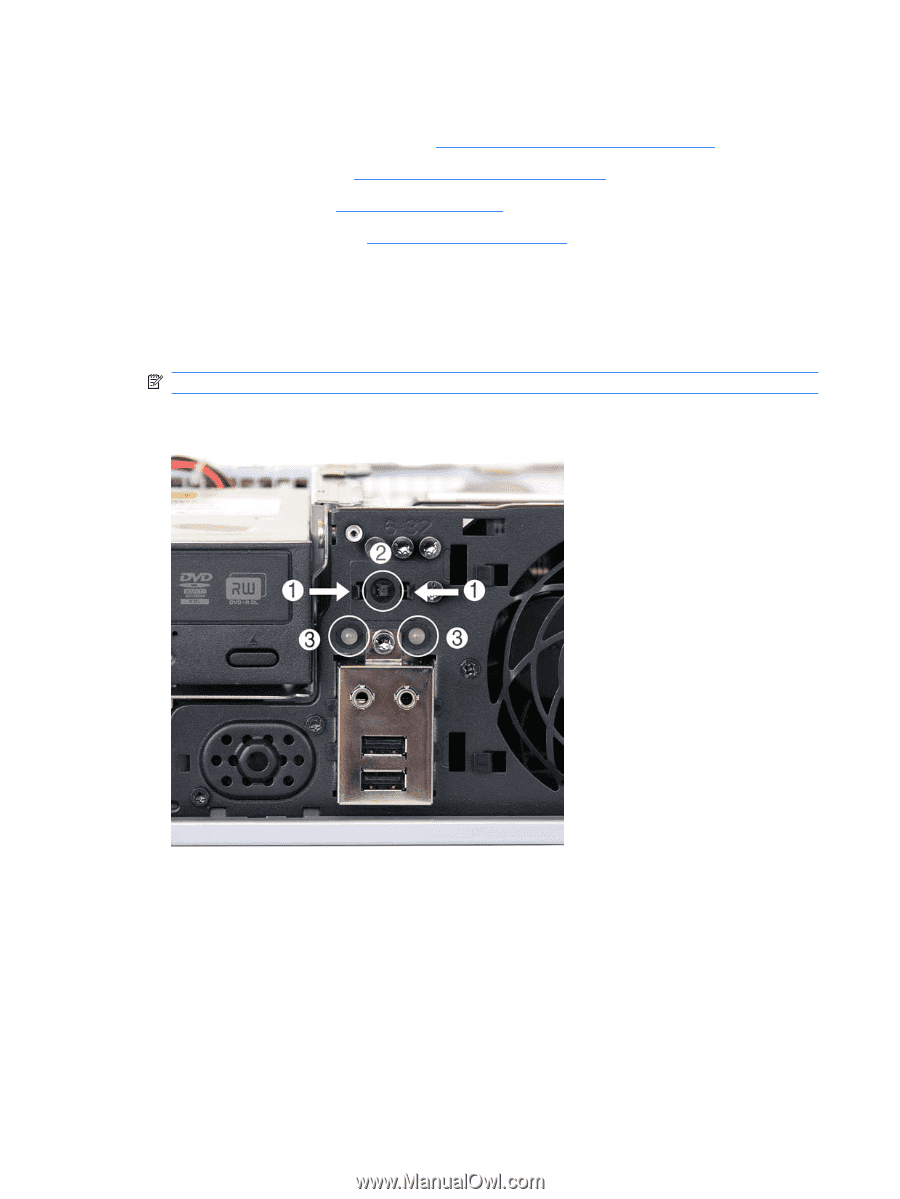
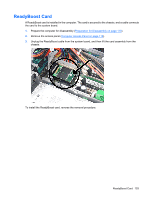
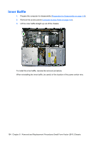
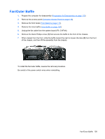
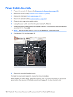
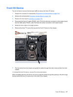
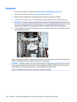
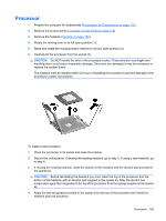
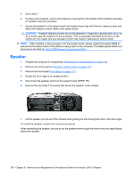
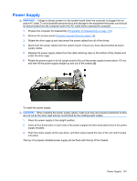
Power Switch Assembly 1. Prepare the computer for disassembly (Preparation for Disassembly on page 110). 2. Remove the access panel (Computer Access Panel on page 116). 3. Remove the front bezel (Front Bezel on page 117). 4. Remove the fan/outer baffle (Fan/Outer Baffle on page 155). 5. Rotate the drive cage to the upright position. 6. Unplug the power switch cable from the system board (P5, PB/LED). 7. Squeeze the switch holder retaining clips together at the front of the chassis (1) and push the switch assembly into the chassis (2). NOTE: Note the location of each LED so you can reassemble in the correct order 8. Push the two LEDs into the chassis (3). 9. Remove the assembly from the chassis. To install the power switch assembly, reverse the removal procedure. When installing the power switch, replace the LEDs first. You may need to first insert one clip and the power button, then use a small flat-blade screwdriver to help guide the other clip into its slot. 156 Chapter 8 Removal and Replacement Procedures Small Form Factor (SFF) Chassis
-
 1
1 -
2
-
3
-
4
-
5
-
6
-
7
-
8
-
9
-
10
-
11
-
12
-
13
-
14
-
15
-
16
-
17
-
18
-
19
-
20
-
21
-
22
-
23
-
24
-
25
-
26
-
27
-
28
-
29
-
30
-
31
-
32
-
33
-
34
-
35
-
36
-
37
-
38
-
39
-
40
-
41
-
42
-
43
-
44
-
45
-
46
-
47
-
48
-
49
-
50
-
51
-
52
-
53
-
54
-
55
-
56
-
57
-
58
-
59
-
60
-
61
-
62
-
63
-
64
-
65
-
66
-
67
-
68
-
69
-
70
-
71
-
72
-
73
-
74
-
75
-
76
-
77
-
78
-
79
-
80
-
81
-
82
-
83
-
84
-
85
-
86
-
87
-
88
-
89
-
90
-
91
-
92
-
93
-
94
-
95
-
96
-
97
-
98
-
99
-
100
-
101
-
102
-
103
-
104
-
105
-
106
-
107
-
108
-
109
-
110
-
111
-
112
-
113
-
114
-
115
-
116
-
117
-
118
-
119
-
120
-
121
-
122
-
123
-
124
-
125
-
126
-
127
-
128
-
129
-
130
-
131
-
132
-
133
-
134
-
135
-
136
-
137
-
138
-
139
-
140
-
141
-
142
-
143
-
144
-
145
-
146
-
147
-
148
-
149
-
150
-
151
-
152
-
153
-
154
-
155
-
156
-
157
-
158
-
 159
159 -
 160
160 -
 161
161 -
 162
162 -
 163
163 -
 164
164 -
 165
165 -
 166
166 -
 167
167 -
 168
168 -
 169
169 -
170
-
171
-
172
-
173
-
174
-
175
-
176
-
177
-
178
-
179
-
180
-
181
-
182
-
183
-
184
-
185
-
186
-
187
-
188
-
189
-
190
-
191
-
192
-
193
-
194
-
195
-
196
-
197
-
198
-
199
-
200
-
201
-
202
-
203
-
204
-
205
-
206
-
207
-
208
-
209
-
210
-
211
-
212
-
213
-
214
-
215
-
216
-
217
-
218
-
219
-
220
-
221
-
222
-
223
-
224
-
225
-
226
-
227
-
228
-
229
-
230
-
231
-
232
-
233
-
234
-
235
-
236
-
237
-
238
-
239
-
240
-
241
-
242
-
243
-
244
-
245
-
246
-
247
-
248
-
249
-
250
-
251
-
252
-
253
-
254
-
255
 |
 |