HP Dc5800 Service Reference Guide: HP Compaq dc5800 Business PC - Page 165
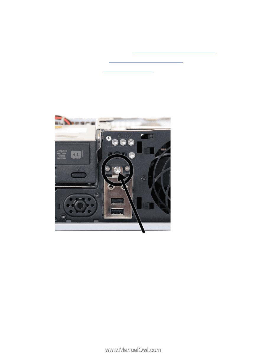
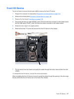
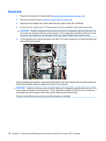
Front I/O Device, Remove the silver T15 screw that secures the front I/O device to the chassis.
 |
UPC - 883585860944
View all HP Dc5800 manuals
Add to My Manuals
Save this manual to your list of manuals |
Page 165 highlights
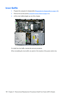
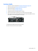
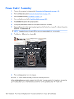
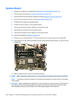
Front I/O Device You do not have to remove the fan/outer baffle to remove the front I/O device. 1. Prepare the computer for disassembly (Preparation for Disassembly on page 110). 2. Remove the access panel (Computer Access Panel on page 116). 3. Remove the front bezel (Front Bezel on page 117). 4. Disconnect the front I/O cable (FRONT_AUD, P23) from the blue connector on the system board and the USB cable (FRONT_USB, P24) from the yellow connector on the system board. 5. Rotate the drive cage to its upright position. 6. Remove the silver T15 screw that secures the front I/O device to the chassis. 7. Pull the device from the chassis and guide the cables through the hole to remove them from the chassis. To reinstall the front I/O device, reverse the removal procedure. When reinstalling the front I/O device, be sure to guide the cables through the opening in the drive cage directly behind the front I/O device slot in the front of the chassis. Front I/O Device 157
-
 1
1 -
2
-
3
-
4
-
5
-
6
-
7
-
8
-
9
-
10
-
11
-
12
-
13
-
14
-
15
-
16
-
17
-
18
-
19
-
20
-
21
-
22
-
23
-
24
-
25
-
26
-
27
-
28
-
29
-
30
-
31
-
32
-
33
-
34
-
35
-
36
-
37
-
38
-
39
-
40
-
41
-
42
-
43
-
44
-
45
-
46
-
47
-
48
-
49
-
50
-
51
-
52
-
53
-
54
-
55
-
56
-
57
-
58
-
59
-
60
-
61
-
62
-
63
-
64
-
65
-
66
-
67
-
68
-
69
-
70
-
71
-
72
-
73
-
74
-
75
-
76
-
77
-
78
-
79
-
80
-
81
-
82
-
83
-
84
-
85
-
86
-
87
-
88
-
89
-
90
-
91
-
92
-
93
-
94
-
95
-
96
-
97
-
98
-
99
-
100
-
101
-
102
-
103
-
104
-
105
-
106
-
107
-
108
-
109
-
110
-
111
-
112
-
113
-
114
-
115
-
116
-
117
-
118
-
119
-
120
-
121
-
122
-
123
-
124
-
125
-
126
-
127
-
128
-
129
-
130
-
131
-
132
-
133
-
134
-
135
-
136
-
137
-
138
-
139
-
140
-
141
-
142
-
143
-
144
-
145
-
146
-
147
-
148
-
149
-
150
-
151
-
152
-
153
-
154
-
155
-
156
-
157
-
158
-
159
-
 160
160 -
 161
161 -
 162
162 -
 163
163 -
 164
164 -
 165
165 -
 166
166 -
 167
167 -
 168
168 -
 169
169 -
 170
170 -
171
-
172
-
173
-
174
-
175
-
176
-
177
-
178
-
179
-
180
-
181
-
182
-
183
-
184
-
185
-
186
-
187
-
188
-
189
-
190
-
191
-
192
-
193
-
194
-
195
-
196
-
197
-
198
-
199
-
200
-
201
-
202
-
203
-
204
-
205
-
206
-
207
-
208
-
209
-
210
-
211
-
212
-
213
-
214
-
215
-
216
-
217
-
218
-
219
-
220
-
221
-
222
-
223
-
224
-
225
-
226
-
227
-
228
-
229
-
230
-
231
-
232
-
233
-
234
-
235
-
236
-
237
-
238
-
239
-
240
-
241
-
242
-
243
-
244
-
245
-
246
-
247
-
248
-
249
-
250
-
251
-
252
-
253
-
254
-
255
 |
 |