HP Dc5800 Service Reference Guide: HP Compaq dc5800 Business PC - Page 170
Preparation for Disassembly, on Computer Access Panel, Expansion Cards, Inner Baffle, Heatsink
 |
UPC - 883585860944
View all HP Dc5800 manuals
Add to My Manuals
Save this manual to your list of manuals |
Page 170 highlights
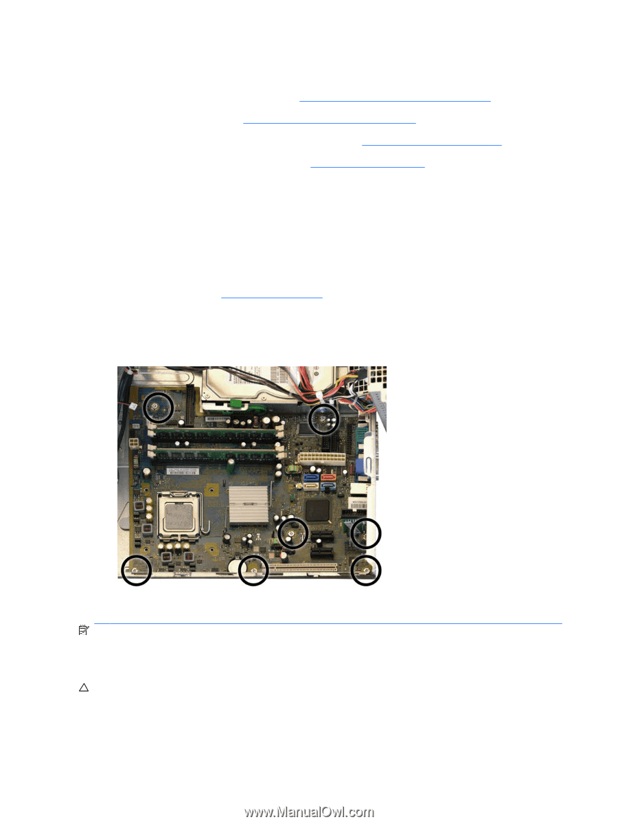
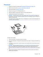
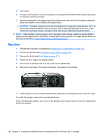
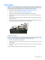
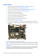
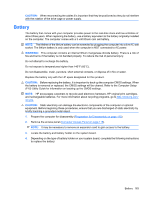
System Board 1. Prepare the computer for disassembly (Preparation for Disassembly on page 110). 2. Remove the access panel (Computer Access Panel on page 116). 3. Remove all PCI and PCI Express expansion boards (Expansion Cards on page 125). 4. Remove the fan shroud from the chassis (Inner Baffle on page 154). 5. Rotate the drive cage to its upright position. 6. Rotate the power supply to its full upright position. 7. Disconnect all data and power cables from the system board. 8. Disconnect the serial port from the system board. 9. Disconnect the balance of the cables from the system board. 10. Remove the heatsink (Heatsink on page 158). 11. Remove the six remaining silver T15 screws that secure the system board to the chassis (1). 12. Lift up the front of the system board (2), and then pull the system board forward, up, and out of the chassis (3). To install the system board, reverse the removal procedure. NOTE: When replacing the system board, you must change the chassis serial number in the BIOS. NOTE: The heatsink should be installed on the system board before the system board is reinstalled in the chassis. CAUTION: Before reinstalling the heatsink you must clean the top of the processor and the bottom of the heatsink with an alcohol pad supplied in the spares kit. After the alcohol has evaporated, apply thermal grease to the top of the processor from the syringe supplied in the spares kit. 162 Chapter 8 Removal and Replacement Procedures Small Form Factor (SFF) Chassis
-
 1
1 -
2
-
3
-
4
-
5
-
6
-
7
-
8
-
9
-
10
-
11
-
12
-
13
-
14
-
15
-
16
-
17
-
18
-
19
-
20
-
21
-
22
-
23
-
24
-
25
-
26
-
27
-
28
-
29
-
30
-
31
-
32
-
33
-
34
-
35
-
36
-
37
-
38
-
39
-
40
-
41
-
42
-
43
-
44
-
45
-
46
-
47
-
48
-
49
-
50
-
51
-
52
-
53
-
54
-
55
-
56
-
57
-
58
-
59
-
60
-
61
-
62
-
63
-
64
-
65
-
66
-
67
-
68
-
69
-
70
-
71
-
72
-
73
-
74
-
75
-
76
-
77
-
78
-
79
-
80
-
81
-
82
-
83
-
84
-
85
-
86
-
87
-
88
-
89
-
90
-
91
-
92
-
93
-
94
-
95
-
96
-
97
-
98
-
99
-
100
-
101
-
102
-
103
-
104
-
105
-
106
-
107
-
108
-
109
-
110
-
111
-
112
-
113
-
114
-
115
-
116
-
117
-
118
-
119
-
120
-
121
-
122
-
123
-
124
-
125
-
126
-
127
-
128
-
129
-
130
-
131
-
132
-
133
-
134
-
135
-
136
-
137
-
138
-
139
-
140
-
141
-
142
-
143
-
144
-
145
-
146
-
147
-
148
-
149
-
150
-
151
-
152
-
153
-
154
-
155
-
156
-
157
-
158
-
159
-
160
-
161
-
162
-
163
-
164
-
 165
165 -
 166
166 -
 167
167 -
 168
168 -
 169
169 -
 170
170 -
 171
171 -
 172
172 -
 173
173 -
 174
174 -
 175
175 -
176
-
177
-
178
-
179
-
180
-
181
-
182
-
183
-
184
-
185
-
186
-
187
-
188
-
189
-
190
-
191
-
192
-
193
-
194
-
195
-
196
-
197
-
198
-
199
-
200
-
201
-
202
-
203
-
204
-
205
-
206
-
207
-
208
-
209
-
210
-
211
-
212
-
213
-
214
-
215
-
216
-
217
-
218
-
219
-
220
-
221
-
222
-
223
-
224
-
225
-
226
-
227
-
228
-
229
-
230
-
231
-
232
-
233
-
234
-
235
-
236
-
237
-
238
-
239
-
240
-
241
-
242
-
243
-
244
-
245
-
246
-
247
-
248
-
249
-
250
-
251
-
252
-
253
-
254
-
255
 |
 |