HP Dc5800 Service Reference Guide: HP Compaq dc5800 Business PC - Page 80
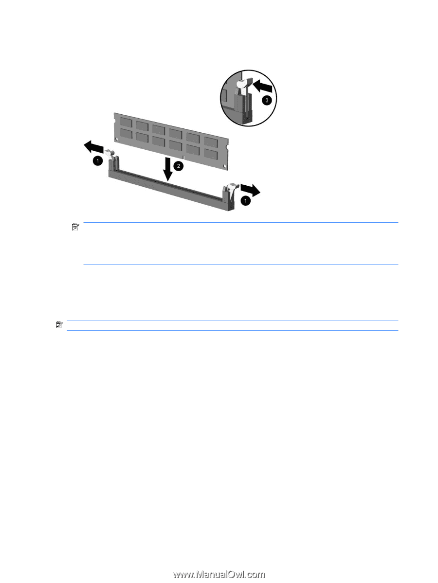
socket to avoid memory corruption. Make sure the latches are in the closed position 3.
 |
UPC - 883585860944
View all HP Dc5800 manuals
Add to My Manuals
Save this manual to your list of manuals |
Page 80 highlights
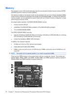
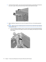
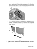
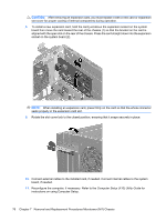
3. Open both latches of the memory module socket (1), and insert the memory module into the socket (2). NOTE: A memory module can be installed in only one way. Match the notch on the module with the tab on the memory socket. A DIMM must occupy the black XMM1 socket. NOTE: For maximum performance, populate the sockets so that the memory capacity is spread as equally as possible between Channel A and Channel B. 4. Push the DIMM module down firmly into the socket, ensuring that the module is fully inserted and properly seated. The DIMM must be pushed all the way down into the socket and sit evenly in the socket to avoid memory corruption. Make sure the latches are in the closed position (3). 5. Repeat steps 3 and 4 for any additional modules that you want to install. NOTE: The computer automatically recognizes the additional memory when turned on. To reassemble the computer, reverse the removal procedure. 72 Chapter 7 Removal and Replacement Procedures Microtower (MT) Chassis
-
 1
1 -
2
-
3
-
4
-
5
-
6
-
7
-
8
-
9
-
10
-
11
-
12
-
13
-
14
-
15
-
16
-
17
-
18
-
19
-
20
-
21
-
22
-
23
-
24
-
25
-
26
-
27
-
28
-
29
-
30
-
31
-
32
-
33
-
34
-
35
-
36
-
37
-
38
-
39
-
40
-
41
-
42
-
43
-
44
-
45
-
46
-
47
-
48
-
49
-
50
-
51
-
52
-
53
-
54
-
55
-
56
-
57
-
58
-
59
-
60
-
61
-
62
-
63
-
64
-
65
-
66
-
67
-
68
-
69
-
70
-
71
-
72
-
73
-
74
-
 75
75 -
 76
76 -
 77
77 -
 78
78 -
 79
79 -
 80
80 -
 81
81 -
 82
82 -
 83
83 -
 84
84 -
 85
85 -
86
-
87
-
88
-
89
-
90
-
91
-
92
-
93
-
94
-
95
-
96
-
97
-
98
-
99
-
100
-
101
-
102
-
103
-
104
-
105
-
106
-
107
-
108
-
109
-
110
-
111
-
112
-
113
-
114
-
115
-
116
-
117
-
118
-
119
-
120
-
121
-
122
-
123
-
124
-
125
-
126
-
127
-
128
-
129
-
130
-
131
-
132
-
133
-
134
-
135
-
136
-
137
-
138
-
139
-
140
-
141
-
142
-
143
-
144
-
145
-
146
-
147
-
148
-
149
-
150
-
151
-
152
-
153
-
154
-
155
-
156
-
157
-
158
-
159
-
160
-
161
-
162
-
163
-
164
-
165
-
166
-
167
-
168
-
169
-
170
-
171
-
172
-
173
-
174
-
175
-
176
-
177
-
178
-
179
-
180
-
181
-
182
-
183
-
184
-
185
-
186
-
187
-
188
-
189
-
190
-
191
-
192
-
193
-
194
-
195
-
196
-
197
-
198
-
199
-
200
-
201
-
202
-
203
-
204
-
205
-
206
-
207
-
208
-
209
-
210
-
211
-
212
-
213
-
214
-
215
-
216
-
217
-
218
-
219
-
220
-
221
-
222
-
223
-
224
-
225
-
226
-
227
-
228
-
229
-
230
-
231
-
232
-
233
-
234
-
235
-
236
-
237
-
238
-
239
-
240
-
241
-
242
-
243
-
244
-
245
-
246
-
247
-
248
-
249
-
250
-
251
-
252
-
253
-
254
-
255
 |
 |