HP Dc5800 Service Reference Guide: HP Compaq dc5800 Business PC - Page 77
Cable Connections, Power Supply Cable Connections
 |
UPC - 883585860944
View all HP Dc5800 manuals
Add to My Manuals
Save this manual to your list of manuals |
Page 77 highlights
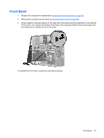
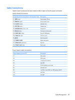
Cable Connections System board connectors are color-coded to make it easier to find the proper connection. System Board Connections System Board Connector, Name, and Connector Color Description P1, PWR, black P3, PWRCPU, black Power supply, 24-pin Power supply, 4-pin P10, FLOPPY, black P8, CPU FAN, white P9, CHASSIS FAN, brown or red Diskette drive Heatsink fan Chassis fan P5, PB/LED, black P24, FRNT USB, Yellow P23, FRNT I/O, black Front power button/LED Front I/O USB cable Front I/O audio P6, SPKR P150, MEDIA CARD P11, REAR FAN, red/maroon P12, FRONT_AUD, white Internal speaker Media card reader Rear fan Front audio Power Supply Cable Connections Power Supply Connector ID P1 P3 P4 P5 P6 P8 P9 P10 P11 Description Main power CPU power 1st Hard drive, SATA0 2nd HDD PATA/Zip/Media card reader Diskette drive 1st ODD or 2nd HDD if no ODD present, SATA1 2nd ODD 3rd ODD Cable Management 69
-
 1
1 -
2
-
3
-
4
-
5
-
6
-
7
-
8
-
9
-
10
-
11
-
12
-
13
-
14
-
15
-
16
-
17
-
18
-
19
-
20
-
21
-
22
-
23
-
24
-
25
-
26
-
27
-
28
-
29
-
30
-
31
-
32
-
33
-
34
-
35
-
36
-
37
-
38
-
39
-
40
-
41
-
42
-
43
-
44
-
45
-
46
-
47
-
48
-
49
-
50
-
51
-
52
-
53
-
54
-
55
-
56
-
57
-
58
-
59
-
60
-
61
-
62
-
63
-
64
-
65
-
66
-
67
-
68
-
69
-
70
-
71
-
 72
72 -
 73
73 -
 74
74 -
 75
75 -
 76
76 -
 77
77 -
 78
78 -
 79
79 -
 80
80 -
 81
81 -
 82
82 -
83
-
84
-
85
-
86
-
87
-
88
-
89
-
90
-
91
-
92
-
93
-
94
-
95
-
96
-
97
-
98
-
99
-
100
-
101
-
102
-
103
-
104
-
105
-
106
-
107
-
108
-
109
-
110
-
111
-
112
-
113
-
114
-
115
-
116
-
117
-
118
-
119
-
120
-
121
-
122
-
123
-
124
-
125
-
126
-
127
-
128
-
129
-
130
-
131
-
132
-
133
-
134
-
135
-
136
-
137
-
138
-
139
-
140
-
141
-
142
-
143
-
144
-
145
-
146
-
147
-
148
-
149
-
150
-
151
-
152
-
153
-
154
-
155
-
156
-
157
-
158
-
159
-
160
-
161
-
162
-
163
-
164
-
165
-
166
-
167
-
168
-
169
-
170
-
171
-
172
-
173
-
174
-
175
-
176
-
177
-
178
-
179
-
180
-
181
-
182
-
183
-
184
-
185
-
186
-
187
-
188
-
189
-
190
-
191
-
192
-
193
-
194
-
195
-
196
-
197
-
198
-
199
-
200
-
201
-
202
-
203
-
204
-
205
-
206
-
207
-
208
-
209
-
210
-
211
-
212
-
213
-
214
-
215
-
216
-
217
-
218
-
219
-
220
-
221
-
222
-
223
-
224
-
225
-
226
-
227
-
228
-
229
-
230
-
231
-
232
-
233
-
234
-
235
-
236
-
237
-
238
-
239
-
240
-
241
-
242
-
243
-
244
-
245
-
246
-
247
-
248
-
249
-
250
-
251
-
252
-
253
-
254
-
255
 |
 |