HP Dc7900 Service Reference Guide: HP Compaq dc7900 Business PC - Page 10

Appendix A, Connector Pin Assignments, Power Cord Set Requirements, POST Error Messages - sff specifications

Page 10 highlights

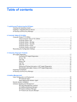
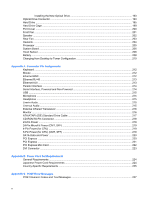
Installing the New Optical Drive 193 Optical Drive Connector ...193 Hard Drive ...195 Hard Drive Cage ...199 Port Cover ...200 Front Fan ...201 Speaker ...202 Rear Fan ...203 Heatsink ...204 Processor ...205 System Board ...206 Hood Sensor ...208 Battery ...208 Changing from Desktop to Tower Configuration 210 Appendix A Connector Pin Assignments Keyboard ...212 Mouse ...212 Ethernet BNC ...212 Ethernet RJ-45 ...213 Ethernet AUI ...213 Parallel Interface ...214 Serial Interface, Powered and Non-Powered 214 USB ...215 Microphone ...215 Headphone ...215 Line-in Audio ...215 Line-out Audio ...215 External Infrared Transceiver ...216 Monitor ...216 ATA/ATAPI (IDE) Standard Drive Cable 217 CD-ROM 50-Pin Connector ...218 24-Pin Power ...218 24-Pin MicroFit Power (CMT, SFF 219 4-Pin Power (for CPU) ...219 6-Pin Power (for CPU) (CMT, SFF 219 SATA Data and Power ...220 PCI Express ...220 PCI Express ...221 PCI Express Mini Card ...222 DVI Connector ...223 Appendix B Power Cord Set Requirements General Requirements ...224 Japanese Power Cord Requirements 224 Country-Specific Requirements ...225 Appendix C POST Error Messages POST Numeric Codes and Text Messages 227 x

  • 1
  • 2
  • 3
  • 4
  • 5
  • 6
  • 7
  • 8
  • 9
  • 10
  • 11
  • 12
  • 13
  • 14
  • 15
  • 16
  • 17
  • 18
  • 19
  • 20
  • 21
  • 22
  • 23
  • 24
  • 25
  • 26
  • 27
  • 28
  • 29
  • 30
  • 31
  • 32
  • 33
  • 34
  • 35
  • 36
  • 37
  • 38
  • 39
  • 40
  • 41
  • 42
  • 43
  • 44
  • 45
  • 46
  • 47
  • 48
  • 49
  • 50
  • 51
  • 52
  • 53
  • 54
  • 55
  • 56
  • 57
  • 58
  • 59
  • 60
  • 61
  • 62
  • 63
  • 64
  • 65
  • 66
  • 67
  • 68
  • 69
  • 70
  • 71
  • 72
  • 73
  • 74
  • 75
  • 76
  • 77
  • 78
  • 79
  • 80
  • 81
  • 82
  • 83
  • 84
  • 85
  • 86
  • 87
  • 88
  • 89
  • 90
  • 91
  • 92
  • 93
  • 94
  • 95
  • 96
  • 97
  • 98
  • 99
  • 100
  • 101
  • 102
  • 103
  • 104
  • 105
  • 106
  • 107
  • 108
  • 109
  • 110
  • 111
  • 112
  • 113
  • 114
  • 115
  • 116
  • 117
  • 118
  • 119
  • 120
  • 121
  • 122
  • 123
  • 124
  • 125
  • 126
  • 127
  • 128
  • 129
  • 130
  • 131
  • 132
  • 133
  • 134
  • 135
  • 136
  • 137
  • 138
  • 139
  • 140
  • 141
  • 142
  • 143
  • 144
  • 145
  • 146
  • 147
  • 148
  • 149
  • 150
  • 151
  • 152
  • 153
  • 154
  • 155
  • 156
  • 157
  • 158
  • 159
  • 160
  • 161
  • 162
  • 163
  • 164
  • 165
  • 166
  • 167
  • 168
  • 169
  • 170
  • 171
  • 172
  • 173
  • 174
  • 175
  • 176
  • 177
  • 178
  • 179
  • 180
  • 181
  • 182
  • 183
  • 184
  • 185
  • 186
  • 187
  • 188
  • 189
  • 190
  • 191
  • 192
  • 193
  • 194
  • 195
  • 196
  • 197
  • 198
  • 199
  • 200
  • 201
  • 202
  • 203
  • 204
  • 205
  • 206
  • 207
  • 208
  • 209
  • 210
  • 211
  • 212
  • 213
  • 214
  • 215
  • 216
  • 217
  • 218
  • 219
  • 220
  • 221
  • 222
  • 223
  • 224
  • 225
  • 226
  • 227
  • 228
  • 229
  • 230
  • 231
  • 232
  • 233
  • 234
  • 235
  • 236
  • 237
  • 238
  • 239
  • 240
  • 241
  • 242
  • 243
  • 244
  • 245
  • 246
  • 247
  • 248
  • 249
  • 250
  • 251
  • 252
  • 253
  • 254
  • 255
  • 256
  • 257
  • 258
  • 259
  • 260
  • 261
  • 262
  • 263
  • 264
  • 265
  • 266
  • 267
  • 268
  • 269
  • 270
  • 271
  • 272
  • 273
  • 274
  • 275
  • 276
  • 277
  • 278
  • 279
  • 280
  • 281
  • 282
  • 283
  • 284
  • 285
  • 286
  • 287
  • 288
  • 289
  • 290
  • 291
  • 292
  • 293
  • 294
  • 295
  • 296
  • 297
  • 298
  • 299
  • 300

Installing the New Optical Drive
.......................................................................................
193
Optical Drive Connector
...................................................................................................................
193
Hard Drive
........................................................................................................................................
195
Hard Drive Cage
...............................................................................................................................
199
Port Cover
........................................................................................................................................
200
Front Fan
..........................................................................................................................................
201
Speaker
............................................................................................................................................
202
Rear Fan
..........................................................................................................................................
203
Heatsink
...........................................................................................................................................
204
Processor
.........................................................................................................................................
205
System Board
...................................................................................................................................
206
Hood Sensor
....................................................................................................................................
208
Battery
..............................................................................................................................................
208
Changing from Desktop to Tower Configuration
..............................................................................
210
Appendix A
Connector Pin Assignments
Keyboard
..........................................................................................................................................
212
Mouse
...............................................................................................................................................
212
Ethernet BNC
...................................................................................................................................
212
Ethernet RJ-45
.................................................................................................................................
213
Ethernet AUI
.....................................................................................................................................
213
Parallel Interface
..............................................................................................................................
214
Serial Interface, Powered and Non-Powered
...................................................................................
214
USB
..................................................................................................................................................
215
Microphone
.......................................................................................................................................
215
Headphone
.......................................................................................................................................
215
Line-in Audio
....................................................................................................................................
215
Line-out Audio
..................................................................................................................................
215
External Infrared Transceiver
...........................................................................................................
216
Monitor
.............................................................................................................................................
216
ATA/ATAPI (IDE) Standard Drive Cable
..........................................................................................
217
CD-ROM 50-Pin Connector
..............................................................................................................
218
24-Pin Power
....................................................................................................................................
218
24-Pin MicroFit Power (CMT, SFF)
..................................................................................................
219
4-Pin Power (for CPU)
......................................................................................................................
219
6-Pin Power (for CPU) (CMT, SFF)
..................................................................................................
219
SATA Data and Power
.....................................................................................................................
220
PCI Express
....................................................................................................................................
220
PCI Express
.....................................................................................................................................
221
PCI Express Mini Card
.....................................................................................................................
222
DVI Connector
..................................................................................................................................
223
Appendix B
Power Cord Set Requirements
General Requirements
.....................................................................................................................
224
Japanese Power Cord Requirements
..............................................................................................
224
Country-Specific Requirements
........................................................................................................
225
Appendix C
POST Error Messages
POST Numeric Codes and Text Messages
.....................................................................................
227
x