HP Dc7900 Service Reference Guide: HP Compaq dc7900 Business PC - Page 183
System Board,
 |
UPC - 884962028483
View all HP Dc7900 manuals
Add to My Manuals
Save this manual to your list of manuals |
Page 183 highlights
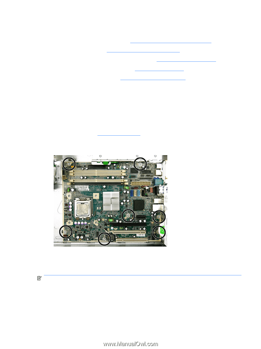
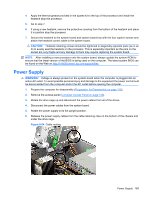
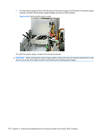
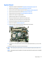
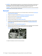
System Board 1. Prepare the computer for disassembly (Preparation for Disassembly on page 118). 2. Remove the access panel (Computer Access Panel on page 125). 3. Remove all PCI and PCI Express expansion boards (Expansion Cards on page 132). 4. Remove the fan shroud from the chassis (Fan Shroud on page 161). 5. Remove the fan from the chassis (Front Fan Assembly on page 162). 6. Rotate the drive cage to its upright position. 7. Rotate the power supply to its full upright position. 8. Disconnect all data and power cables from the system board. 9. If applicable, disconnect the serial port from the system board. 10. Disconnect the balance of the cables from the system board. 11. Remove the heatsink (Heatsink on page 167). 12. Remove the seven screws that secure the system board to the chassis. Figure 8-66 Removing the system board 13. Lift up the front of the system board, and then pull the system board forward, up, and out of the chassis. To install the system board, reverse the removal procedure. NOTE: When replacing the system board, you must also change the chassis serial number in the BIOS. NOTE: The heatsink should be installed on the system board before the system board is reinstalled in the chassis. System Board 171
-
 1
1 -
2
-
3
-
4
-
5
-
6
-
7
-
8
-
9
-
10
-
11
-
12
-
13
-
14
-
15
-
16
-
17
-
18
-
19
-
20
-
21
-
22
-
23
-
24
-
25
-
26
-
27
-
28
-
29
-
30
-
31
-
32
-
33
-
34
-
35
-
36
-
37
-
38
-
39
-
40
-
41
-
42
-
43
-
44
-
45
-
46
-
47
-
48
-
49
-
50
-
51
-
52
-
53
-
54
-
55
-
56
-
57
-
58
-
59
-
60
-
61
-
62
-
63
-
64
-
65
-
66
-
67
-
68
-
69
-
70
-
71
-
72
-
73
-
74
-
75
-
76
-
77
-
78
-
79
-
80
-
81
-
82
-
83
-
84
-
85
-
86
-
87
-
88
-
89
-
90
-
91
-
92
-
93
-
94
-
95
-
96
-
97
-
98
-
99
-
100
-
101
-
102
-
103
-
104
-
105
-
106
-
107
-
108
-
109
-
110
-
111
-
112
-
113
-
114
-
115
-
116
-
117
-
118
-
119
-
120
-
121
-
122
-
123
-
124
-
125
-
126
-
127
-
128
-
129
-
130
-
131
-
132
-
133
-
134
-
135
-
136
-
137
-
138
-
139
-
140
-
141
-
142
-
143
-
144
-
145
-
146
-
147
-
148
-
149
-
150
-
151
-
152
-
153
-
154
-
155
-
156
-
157
-
158
-
159
-
160
-
161
-
162
-
163
-
164
-
165
-
166
-
167
-
168
-
169
-
170
-
171
-
172
-
173
-
174
-
175
-
176
-
177
-
 178
178 -
 179
179 -
 180
180 -
 181
181 -
 182
182 -
 183
183 -
 184
184 -
 185
185 -
 186
186 -
 187
187 -
 188
188 -
189
-
190
-
191
-
192
-
193
-
194
-
195
-
196
-
197
-
198
-
199
-
200
-
201
-
202
-
203
-
204
-
205
-
206
-
207
-
208
-
209
-
210
-
211
-
212
-
213
-
214
-
215
-
216
-
217
-
218
-
219
-
220
-
221
-
222
-
223
-
224
-
225
-
226
-
227
-
228
-
229
-
230
-
231
-
232
-
233
-
234
-
235
-
236
-
237
-
238
-
239
-
240
-
241
-
242
-
243
-
244
-
245
-
246
-
247
-
248
-
249
-
250
-
251
-
252
-
253
-
254
-
255
-
256
-
257
-
258
-
259
-
260
-
261
-
262
-
263
-
264
-
265
-
266
-
267
-
268
-
269
-
270
-
271
-
272
-
273
-
274
-
275
-
276
-
277
-
278
-
279
-
280
-
281
-
282
-
283
-
284
-
285
-
286
-
287
-
288
-
289
-
290
-
291
-
292
-
293
-
294
-
295
-
296
-
297
-
298
-
299
-
300
 |
 |