HP Dc7900 Service Reference Guide: HP Compaq dc7900 Business PC - Page 196
Lifting the Fan Shroud
 |
UPC - 884962028483
View all HP Dc7900 manuals
Add to My Manuals
Save this manual to your list of manuals |
Page 196 highlights
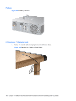
Front Bezel 1. Prepare the computer for disassembly (Preparation for Disassembly on page 178). 2. Remove the computer access panel (Computer Access Panel on page 183). 3. Lift the fan and shroud assembly up and place it on top of the optical drive to access the front bezel release tabs. You do not need to disconnect the fan cable from the system board. Figure 9-9 Lifting the Fan Shroud 4. Press the two release tabs on the inside of the bezel towards the right side of the computer (1) and rotate the bezel off from right to left (2). Figure 9-10 Removing the Front Bezel 5. Replace the fan shroud. To install the front bezel, reverse the removal procedure. 184 Chapter 9 Removal and Replacement Procedures Ultra-Slim Desktop (USDT) Chassis
-
 1
1 -
2
-
3
-
4
-
5
-
6
-
7
-
8
-
9
-
10
-
11
-
12
-
13
-
14
-
15
-
16
-
17
-
18
-
19
-
20
-
21
-
22
-
23
-
24
-
25
-
26
-
27
-
28
-
29
-
30
-
31
-
32
-
33
-
34
-
35
-
36
-
37
-
38
-
39
-
40
-
41
-
42
-
43
-
44
-
45
-
46
-
47
-
48
-
49
-
50
-
51
-
52
-
53
-
54
-
55
-
56
-
57
-
58
-
59
-
60
-
61
-
62
-
63
-
64
-
65
-
66
-
67
-
68
-
69
-
70
-
71
-
72
-
73
-
74
-
75
-
76
-
77
-
78
-
79
-
80
-
81
-
82
-
83
-
84
-
85
-
86
-
87
-
88
-
89
-
90
-
91
-
92
-
93
-
94
-
95
-
96
-
97
-
98
-
99
-
100
-
101
-
102
-
103
-
104
-
105
-
106
-
107
-
108
-
109
-
110
-
111
-
112
-
113
-
114
-
115
-
116
-
117
-
118
-
119
-
120
-
121
-
122
-
123
-
124
-
125
-
126
-
127
-
128
-
129
-
130
-
131
-
132
-
133
-
134
-
135
-
136
-
137
-
138
-
139
-
140
-
141
-
142
-
143
-
144
-
145
-
146
-
147
-
148
-
149
-
150
-
151
-
152
-
153
-
154
-
155
-
156
-
157
-
158
-
159
-
160
-
161
-
162
-
163
-
164
-
165
-
166
-
167
-
168
-
169
-
170
-
171
-
172
-
173
-
174
-
175
-
176
-
177
-
178
-
179
-
180
-
181
-
182
-
183
-
184
-
185
-
186
-
187
-
188
-
189
-
190
-
 191
191 -
 192
192 -
 193
193 -
 194
194 -
 195
195 -
 196
196 -
 197
197 -
 198
198 -
 199
199 -
 200
200 -
 201
201 -
202
-
203
-
204
-
205
-
206
-
207
-
208
-
209
-
210
-
211
-
212
-
213
-
214
-
215
-
216
-
217
-
218
-
219
-
220
-
221
-
222
-
223
-
224
-
225
-
226
-
227
-
228
-
229
-
230
-
231
-
232
-
233
-
234
-
235
-
236
-
237
-
238
-
239
-
240
-
241
-
242
-
243
-
244
-
245
-
246
-
247
-
248
-
249
-
250
-
251
-
252
-
253
-
254
-
255
-
256
-
257
-
258
-
259
-
260
-
261
-
262
-
263
-
264
-
265
-
266
-
267
-
268
-
269
-
270
-
271
-
272
-
273
-
274
-
275
-
276
-
277
-
278
-
279
-
280
-
281
-
282
-
283
-
284
-
285
-
286
-
287
-
288
-
289
-
290
-
291
-
292
-
293
-
294
-
295
-
296
-
297
-
298
-
299
-
300
 |
 |

Front Bezel
1.
Prepare the computer for disassembly (
Preparation for Disassembly
on page
178
).
2.
Remove the computer access panel (
Computer Access Panel
on page
183
).
3.
Lift the fan and shroud assembly up and place it on top of the optical drive to access the front bezel
release tabs. You do not need to disconnect the fan cable from the system board.
Figure 9-9
Lifting the Fan Shroud
4.
Press the two release tabs on the inside of the bezel towards the right side of the computer
(1)
and
rotate the bezel off from right to left
(2)
.
Figure 9-10
Removing the Front Bezel
5.
Replace the fan shroud.
To install the front bezel, reverse the removal procedure.
184
Chapter 9
Removal and Replacement Procedures Ultra-Slim Desktop (USDT) Chassis