HP Dc7900 Service Reference Guide: HP Compaq dc7900 Business PC - Page 126
CAUTION, Installing a Drive in the Desktop Configuration
 |
UPC - 884962028483
View all HP Dc7900 manuals
Add to My Manuals
Save this manual to your list of manuals |
Page 126 highlights
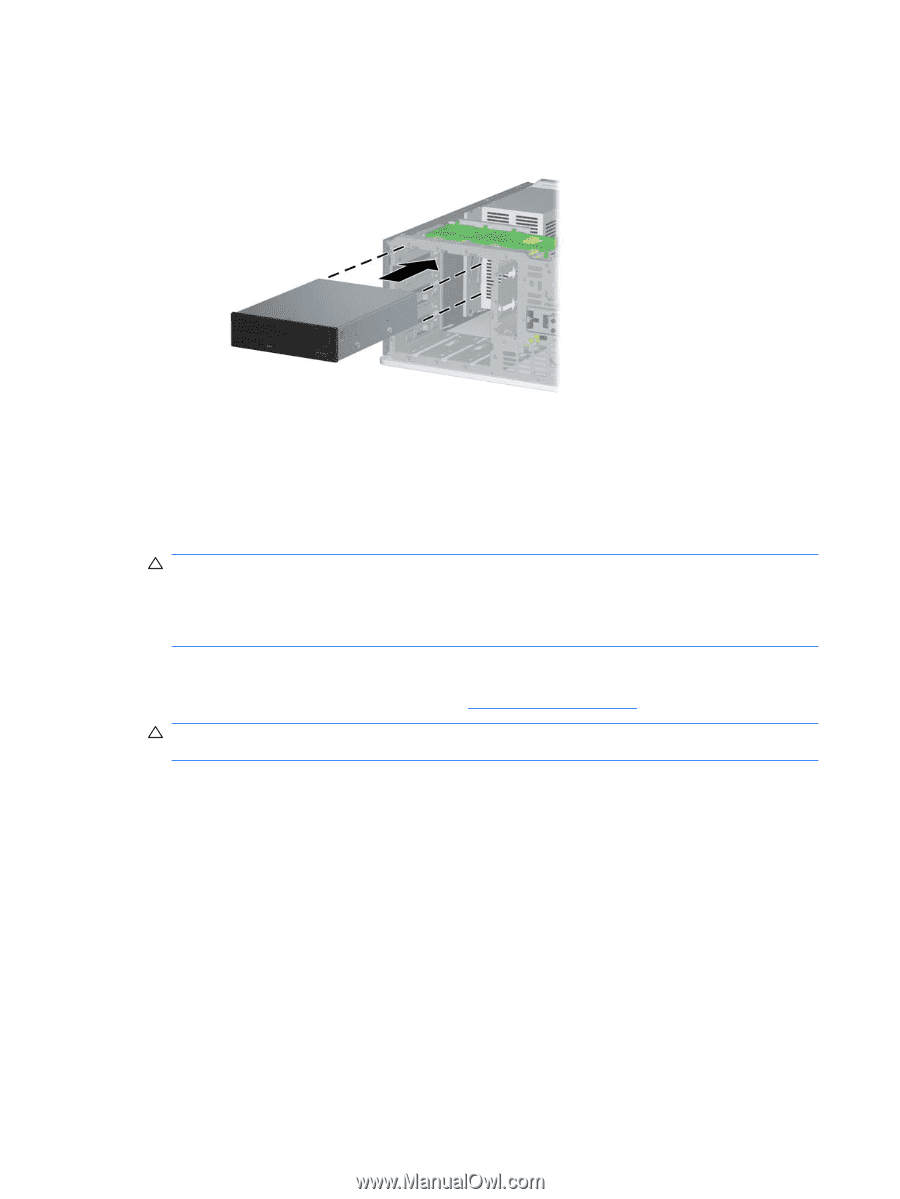
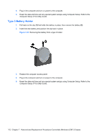
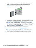
6. Before you reinstall each drive into the chassis, turn the drive so that it is perpendicular to the internal 3.5-inch drive. The drive should be parallel to the green latch drive bracket. Figure 7-59 Installing a Drive in the Desktop Configuration 7. Gently slide the drive into the uppermost available bay until it snaps into place. When the drive is properly inserted, the drivelock will secure it. Repeat this step for each drive. CAUTION: The bottom 5.25-inch drive bay has a shorter depth than the upper two bays. The bottom bay supports a half-height drive or other device that is no more than 14.5 cm (5.7 inches) in depth. Do not try to force a larger drive, such as an optical drive, into the bottom bay. This could cause damage to the drive and the system board. The use of unnecessary force when installing any drive into the drive bay may result in damage to the drive. 8. Reconnect all power and data cables to the drives in the 5.25-inch drive bays. 9. Remove the bezel subpanel as described in Bezel Blanks on page 72. CAUTION: Hold the subpanel straight when you pull it away from the front bezel. Pulling the subpanel away at an angle could damage the pins that align it within the front bezel. 10. Reposition the bezel blanks within the subpanel in the proper orientation for the desktop configuration. 114 Chapter 7 Removal and Replacement Procedures Convertible Minitower (CMT) Chassis
-
 1
1 -
2
-
3
-
4
-
5
-
6
-
7
-
8
-
9
-
10
-
11
-
12
-
13
-
14
-
15
-
16
-
17
-
18
-
19
-
20
-
21
-
22
-
23
-
24
-
25
-
26
-
27
-
28
-
29
-
30
-
31
-
32
-
33
-
34
-
35
-
36
-
37
-
38
-
39
-
40
-
41
-
42
-
43
-
44
-
45
-
46
-
47
-
48
-
49
-
50
-
51
-
52
-
53
-
54
-
55
-
56
-
57
-
58
-
59
-
60
-
61
-
62
-
63
-
64
-
65
-
66
-
67
-
68
-
69
-
70
-
71
-
72
-
73
-
74
-
75
-
76
-
77
-
78
-
79
-
80
-
81
-
82
-
83
-
84
-
85
-
86
-
87
-
88
-
89
-
90
-
91
-
92
-
93
-
94
-
95
-
96
-
97
-
98
-
99
-
100
-
101
-
102
-
103
-
104
-
105
-
106
-
107
-
108
-
109
-
110
-
111
-
112
-
113
-
114
-
115
-
116
-
117
-
118
-
119
-
120
-
 121
121 -
 122
122 -
 123
123 -
 124
124 -
 125
125 -
 126
126 -
 127
127 -
 128
128 -
 129
129 -
 130
130 -
 131
131 -
132
-
133
-
134
-
135
-
136
-
137
-
138
-
139
-
140
-
141
-
142
-
143
-
144
-
145
-
146
-
147
-
148
-
149
-
150
-
151
-
152
-
153
-
154
-
155
-
156
-
157
-
158
-
159
-
160
-
161
-
162
-
163
-
164
-
165
-
166
-
167
-
168
-
169
-
170
-
171
-
172
-
173
-
174
-
175
-
176
-
177
-
178
-
179
-
180
-
181
-
182
-
183
-
184
-
185
-
186
-
187
-
188
-
189
-
190
-
191
-
192
-
193
-
194
-
195
-
196
-
197
-
198
-
199
-
200
-
201
-
202
-
203
-
204
-
205
-
206
-
207
-
208
-
209
-
210
-
211
-
212
-
213
-
214
-
215
-
216
-
217
-
218
-
219
-
220
-
221
-
222
-
223
-
224
-
225
-
226
-
227
-
228
-
229
-
230
-
231
-
232
-
233
-
234
-
235
-
236
-
237
-
238
-
239
-
240
-
241
-
242
-
243
-
244
-
245
-
246
-
247
-
248
-
249
-
250
-
251
-
252
-
253
-
254
-
255
-
256
-
257
-
258
-
259
-
260
-
261
-
262
-
263
-
264
-
265
-
266
-
267
-
268
-
269
-
270
-
271
-
272
-
273
-
274
-
275
-
276
-
277
-
278
-
279
-
280
-
281
-
282
-
283
-
284
-
285
-
286
-
287
-
288
-
289
-
290
-
291
-
292
-
293
-
294
-
295
-
296
-
297
-
298
-
299
-
300
 |
 |