HP OmniBook xe3-gc HP OmniBook Notebook PC XE3 Series - Reference Guide - Page 138
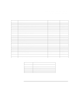
PTT testing of signal level: 00-09=DTMF dial 0-9, 0A=DTMF *, 0B=DTMF #, 0C=DTMF A, 0D=DTMF B
 |
View all HP OmniBook xe3-gc manuals
Add to My Manuals
Save this manual to your list of manuals |
Page 138 highlights
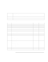
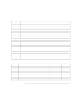
Specifications and Regulatory Information Modem Reference Information Command &P3 &Q0 &Q1 &Q2 &Q3 &Q4 &Q5 &Q6 &R0 &R1 &S0 &S1 &T0 &T1 &T2 &T3 &T4 &T5 &T6 &T7 &T6 &T7 &T8 &V &V1 &W0 &W1 &X0 &X1 &X2 &Y0 &Y1 &Zn=x %E0 %E1 %E2 %L %Q %TTn Function (Ambit) Set 20 pps pulse dial with 33%/67% make/break Select direct asynchronous mode Select sync connect with async off-line command mode Select sync connect with async off-line command mode and enable DTR dialing of directory zero Select sync connect with async off-line command mode and enable DTR to act as Talk/Data switch Select Hayes AutoSync mode Modem negotiates an error corrected link Select asynchronous operation in normal mode CTS tracks RTS (sync) or CTS is normally ON and will turn OFF only if required by flow control (async) CTS is always active (sync) or CTS is normally ON and will turn OFF only if required by flow control (async) DSR is always active DSR will become active after answer tone has been detected and inactive after the carrier has been lost Terminate any test in progress Initiate local analog loopback Returns ERROR result code Initiate local digital loopback Allow remote digital loopback (RDL) Disallow remote digital loopback request Request an RDL without self-test Request an RDL with self-test Request an RDL without self-test Request an RDL with self-test Initiate local analog loop with self-test Display current configuration and stored profiles Display last connection statistics Store the current configuration as profile 0 Store the current configuration as profile 1 Select internal timing for the transmit clock Select external timing for the transmit clock Select slave receive timing for the transmit clock Recall stored profile 0 upon power up Recall stored profile 1 upon power up Store dial string x (up to 34 digits) to location n (0 to 3) Disable line quality monitor and auto retrain Enable line quality monitor and auto retrain Enable line quality monitor and fallback/fall forward Return received line signal level Report the line signal quality PTT testing of signal level: 00-09=DTMF dial 0-9, 0A=DTMF *, 0B=DTMF #, 0C=DTMF A, 0D=DTMF B, 0E=DTMF C, 0F=DTMF D, 10=V.21 Channel 1mark symbol, 11=V.21 Channel 2mark symbol, 15=V.22 originate signaling at 1200bps, 16=V.22bis originate signaling at 2400bps, 17=V.22 answering signaling , 18=V.22bis answer signaling, 19=V.21 Channel 1space symbol, 1A=V.21 Channel 2 space symbol, 20=V.32 9600bps, 21=V.32bis 14400bps, 30=Silence, 31=V.25 answer tone, 32=1800Hz guard tone, 33=V.25 calling tone (1300Hz), 34=Fax calling tone (1100Hz), 40=V.21 channel 2, 41=V.27ter 2400bps, 42=V.27ter 4800bps, 43=V.29 7200bps, 44=V.29 9600bps, 45=V.17 7200bps long, 46=V.17 7200bps short, 47=V.17 9600bps long, 48=V.17 9600bps short, 49=V.17 12000bps long, 4A=V.17 12000bps short, 4B=V.17 14400bps long, 4C=V.17 14400bps short, 60=2400bps (V.34 only), 61=4800bps (V.34 only), 62=7200bps (V.34 only), 63=9600bps (V.34 only), 64=12000bps (V.34 only), 65=14400bps, 66=16800bps, 67=19200bps, 68=21600bps, 69=24000bps, 6A=26400bps, 6B=28800bps, 6C=31200bps, 6D=33600bps 138 Reference Guide
-
 1
1 -
2
-
3
-
4
-
5
-
6
-
7
-
8
-
9
-
10
-
11
-
12
-
13
-
14
-
15
-
16
-
17
-
18
-
19
-
20
-
21
-
22
-
23
-
24
-
25
-
26
-
27
-
28
-
29
-
30
-
31
-
32
-
33
-
34
-
35
-
36
-
37
-
38
-
39
-
40
-
41
-
42
-
43
-
44
-
45
-
46
-
47
-
48
-
49
-
50
-
51
-
52
-
53
-
54
-
55
-
56
-
57
-
58
-
59
-
60
-
61
-
62
-
63
-
64
-
65
-
66
-
67
-
68
-
69
-
70
-
71
-
72
-
73
-
74
-
75
-
76
-
77
-
78
-
79
-
80
-
81
-
82
-
83
-
84
-
85
-
86
-
87
-
88
-
89
-
90
-
91
-
92
-
93
-
94
-
95
-
96
-
97
-
98
-
99
-
100
-
101
-
102
-
103
-
104
-
105
-
106
-
107
-
108
-
109
-
110
-
111
-
112
-
113
-
114
-
115
-
116
-
117
-
118
-
119
-
120
-
121
-
122
-
123
-
124
-
125
-
126
-
127
-
128
-
129
-
130
-
131
-
132
-
 133
133 -
 134
134 -
 135
135 -
 136
136 -
 137
137 -
 138
138 -
 139
139 -
 140
140 -
 141
141 -
 142
142 -
 143
143 -
144
-
145
-
146
-
147
-
148
-
149
-
150
-
151
 |
 |