HP Vectra VEi8 HP Vectra VEi7, User's Guide - Page 34
Replacing the CD-ROM, CD-RW, or DVD Drive
 |
View all HP Vectra VEi8 manuals
Add to My Manuals
Save this manual to your list of manuals |
Page 34 highlights
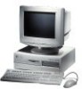
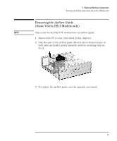
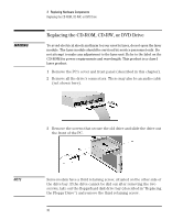
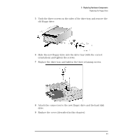
WARNING 3 Replacing Hardware Components Replacing the CD-ROM, CD-RW, or DVD Drive Replacing the CD-ROM, CD-RW, or DVD Drive To avoid electrical shock and harm to your eyes by laser, do not open the laser module. The laser module should be serviced by service personnel only. Do not attempt to make any adjustment to the laser unit. Refer to the label on the CD-ROM for power requirements and wavelength. This product is a class I laser product. 1 Remove the PC's cover and front panel (described in this chapter). 2 Remove all the drive's connectors. There may also be an audio cable (not shown here). 3 Remove the screws that secure the old drive and slide the drive out the front of the PC. Optional third screw NOTE Some models have a third retaining screw, situated on the other side of the drive bay. If the drive cannot be slid out after removing the two screws, take out the floppy/hard disk drive bay (described in "Replacing the Floppy Drive") and remove the third retaining screw. 30 English
-
 1
1 -
2
-
3
-
4
-
5
-
6
-
7
-
8
-
9
-
10
-
11
-
12
-
13
-
14
-
15
-
16
-
17
-
18
-
19
-
20
-
21
-
22
-
23
-
24
-
25
-
26
-
27
-
28
-
 29
29 -
 30
30 -
 31
31 -
 32
32 -
 33
33 -
 34
34 -
 35
35 -
 36
36 -
 37
37 -
 38
38 -
 39
39 -
40
-
41
-
42
-
43
-
44
-
45
-
46
-
47
-
48
-
49
-
50
-
51
-
52
-
53
-
54
-
55
-
56
-
57
-
58
-
59
-
60
-
61
-
62
-
63
-
64
-
65
-
66
-
67
-
68
-
69
-
70
 |
 |