HP ap5000 Maintenance and Service Guide: HP ap5000 All-In-One Point of Sale Sy - Page 52
Routing Cables, Adjusting the Tilt
 |
View all HP ap5000 manuals
Add to My Manuals
Save this manual to your list of manuals |
Page 52 highlights
Routing Cables When connecting peripherals to the bottom I/O panel, route the peripheral cables through the bottom of the base and out the center hole at the top of the base before connecting. Figure 7-4 Routing Cables Adjusting the Tilt The main touch screen display has a 90 degree tilt range. The VFD customer display has an 80 degree tilt range. Figure 7-5 Adjusting the Touch Screen Display Tilt 44 Chapter 7 Removal and Replacement Procedures
-
 1
1 -
2
-
3
-
4
-
5
-
6
-
7
-
8
-
9
-
10
-
11
-
12
-
13
-
14
-
15
-
16
-
17
-
18
-
19
-
20
-
21
-
22
-
23
-
24
-
25
-
26
-
27
-
28
-
29
-
30
-
31
-
32
-
33
-
34
-
35
-
36
-
37
-
38
-
39
-
40
-
41
-
42
-
43
-
44
-
45
-
46
-
 47
47 -
 48
48 -
 49
49 -
 50
50 -
 51
51 -
 52
52 -
 53
53 -
 54
54 -
 55
55 -
 56
56 -
 57
57 -
58
-
59
-
60
-
61
-
62
-
63
-
64
-
65
-
66
-
67
-
68
-
69
-
70
-
71
-
72
-
73
-
74
-
75
-
76
-
77
-
78
-
79
-
80
-
81
-
82
-
83
-
84
-
85
-
86
-
87
-
88
-
89
 |
 |

Routing Cables
When connecting peripherals to the bottom I/O panel, route the peripheral cables through the bottom
of the base and out the center hole at the top of the base before connecting.
Figure 7-4
Routing Cables
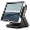
Adjusting the Tilt
The main touch screen display has a 90 degree tilt range. The VFD customer display has an 80
degree tilt range.
Figure 7-5
Adjusting the Touch Screen Display Tilt
44
Chapter 7
Removal and Replacement Procedures