HP ap5000 Maintenance and Service Guide: HP ap5000 All-In-One Point of Sale Sy - Page 74
Monitor, Appendix A, Connector Pin Assignments
 |
View all HP ap5000 manuals
Add to My Manuals
Save this manual to your list of manuals |
Page 74 highlights
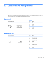
Monitor Connector and Icon Pin Signal Pin Signal 1 Red Analog 9 +5V (fused) 2 Green Analog 10 Ground 3 Blue Analog 11 19V when the 10.4" LCD is detected, 0V when a standard monitor is detected 4 19V when the 10.4" LCD is detected, 0V 12 when a standard monitor is detected DDC Serial Data 5 Ground 13 Horizontal Sync 6 Ground 14 Vertical Sync 7 Ground 15 DDC Serial Clock 8 Ground 66 Appendix A Connector Pin Assignments
-
 1
1 -
2
-
3
-
4
-
5
-
6
-
7
-
8
-
9
-
10
-
11
-
12
-
13
-
14
-
15
-
16
-
17
-
18
-
19
-
20
-
21
-
22
-
23
-
24
-
25
-
26
-
27
-
28
-
29
-
30
-
31
-
32
-
33
-
34
-
35
-
36
-
37
-
38
-
39
-
40
-
41
-
42
-
43
-
44
-
45
-
46
-
47
-
48
-
49
-
50
-
51
-
52
-
53
-
54
-
55
-
56
-
57
-
58
-
59
-
60
-
61
-
62
-
63
-
64
-
65
-
66
-
67
-
68
-
 69
69 -
 70
70 -
 71
71 -
 72
72 -
 73
73 -
 74
74 -
 75
75 -
 76
76 -
 77
77 -
 78
78 -
 79
79 -
80
-
81
-
82
-
83
-
84
-
85
-
86
-
87
-
88
-
89
 |
 |

Monitor
Connector and Icon
Pin
Signal
Pin
Signal
1
2
3
4
Red Analog
Green Analog
Blue Analog
19V when the 10.4” LCD is detected, 0V
when a standard monitor is detected
9
10
11
12
+5V (fused)
Ground
19V when the 10.4” LCD is detected, 0V
when a standard monitor is detected
DDC Serial Data
5
6
7
8
Ground
Ground
Ground
Ground
13
14
15
Horizontal Sync
Vertical Sync
DDC Serial Clock
66
Appendix A
Connector Pin Assignments