HP ap5000 Maintenance and Service Guide: HP ap5000 All-In-One Point of Sale Sy - Page 57
Covering the VFD Customer Display Slot
 |
View all HP ap5000 manuals
Add to My Manuals
Save this manual to your list of manuals |
Page 57 highlights
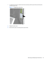
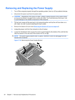
6. Remove the two screws below the display screen (1) and slide the display off the system (2). Figure 7-11 Removing the VFD Customer Display 7. Route the serial cable of the new display through the center hole in the hinge area and connect the cable to the same COM port on the I/O panel that was used for the old display. NOTE: If you are replacing the VFD customer display with an LCD customer display, connect the VGA cable of the LCD customer display to the VGA connector on the I/O panel. 8. If you are removing but not replacing the customer display, cover the slot for the display with the customer display cover provided with the system. Slide the top of the cover in first (1) then press the bottom of the cover in place (2). Figure 7-12 Covering the VFD Customer Display Slot Removing and Replacing the VFD Customer Display 49
-
 1
1 -
2
-
3
-
4
-
5
-
6
-
7
-
8
-
9
-
10
-
11
-
12
-
13
-
14
-
15
-
16
-
17
-
18
-
19
-
20
-
21
-
22
-
23
-
24
-
25
-
26
-
27
-
28
-
29
-
30
-
31
-
32
-
33
-
34
-
35
-
36
-
37
-
38
-
39
-
40
-
41
-
42
-
43
-
44
-
45
-
46
-
47
-
48
-
49
-
50
-
51
-
 52
52 -
 53
53 -
 54
54 -
 55
55 -
 56
56 -
 57
57 -
 58
58 -
 59
59 -
 60
60 -
 61
61 -
 62
62 -
63
-
64
-
65
-
66
-
67
-
68
-
69
-
70
-
71
-
72
-
73
-
74
-
75
-
76
-
77
-
78
-
79
-
80
-
81
-
82
-
83
-
84
-
85
-
86
-
87
-
88
-
89
 |
 |
