HP dx7510 Service Reference Guide: HP Compaq dx7510/dx7518 Business PC - Page 104
HP Business PC Security, expansion card sockets
 |
View all HP dx7510 manuals
Add to My Manuals
Save this manual to your list of manuals |
Page 104 highlights
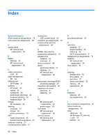
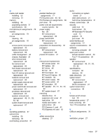
Index Symbols/Numerics 24-pin power pin assignments 79 4-pin power pin assignments 82 A access panel MT removal and replacement 33 B battery disposal 30 MT removal and replacement 68 C cable connections CMT 45 cable management MT 44 cable pinouts SATA data 21 cautions AC power 23 cables 30 cooling fan 29 electrostatic discharge 24 keyboard cleaning 28 keyboard keys 28 chassis MT illustrated 23 cleaning computer 27 mouse 29 safety precautions 27 CMT cable connections 45 system board connections 45 computer cleaning 27 connecting drive cables 47 connections CMT system board 45 connector pin assignments 76 country power cord set requirements 84 D DIMMs. See memory disassembly preparation 32 diskette drive installing 53 removing 51 drive connectors 48 drives connecting cables 47 installing 47 MT removal and replacement 46 E electrostatic discharge (ESD) preventing damage 25 expansion card sockets 40 expansion slot cover removing 41 replacing 43 F fan MT removal and replacement 63 power supply 29 front bezel MT removal and replacement 34 front I/O device MT removal and replacement 60 G grounding methods 25 H hard drive installing 57 proper handling 30 removing 54 SATA characteristics 21 headphone pin assignments 78 heatsink MT removal and replacement 64 hood sensor 75 I installing diskette drive 53 drive cables 47 hard drive 57 media card reader 53 memory 36 optical drive 50 K keyboard cleaning 28 pin assignments 76 L line-in audio pin assignments 78 line-out audio pin assignments 78 locks cable lock 72 HP Business PC Security Lock 73 padlock 72 96 Index
-
 1
1 -
2
-
3
-
4
-
5
-
6
-
7
-
8
-
9
-
10
-
11
-
12
-
13
-
14
-
15
-
16
-
17
-
18
-
19
-
20
-
21
-
22
-
23
-
24
-
25
-
26
-
27
-
28
-
29
-
30
-
31
-
32
-
33
-
34
-
35
-
36
-
37
-
38
-
39
-
40
-
41
-
42
-
43
-
44
-
45
-
46
-
47
-
48
-
49
-
50
-
51
-
52
-
53
-
54
-
55
-
56
-
57
-
58
-
59
-
60
-
61
-
62
-
63
-
64
-
65
-
66
-
67
-
68
-
69
-
70
-
71
-
72
-
73
-
74
-
75
-
76
-
77
-
78
-
79
-
80
-
81
-
82
-
83
-
84
-
85
-
86
-
87
-
88
-
89
-
90
-
91
-
92
-
93
-
94
-
95
-
96
-
97
-
98
-
 99
99 -
 100
100 -
 101
101 -
 102
102 -
 103
103 -
 104
104 -
 105
105
 |
 |