HP dx7510 Service Reference Guide: HP Compaq dx7510/dx7518 Business PC - Page 75
System Board
 |
View all HP dx7510 manuals
Add to My Manuals
Save this manual to your list of manuals |
Page 75 highlights
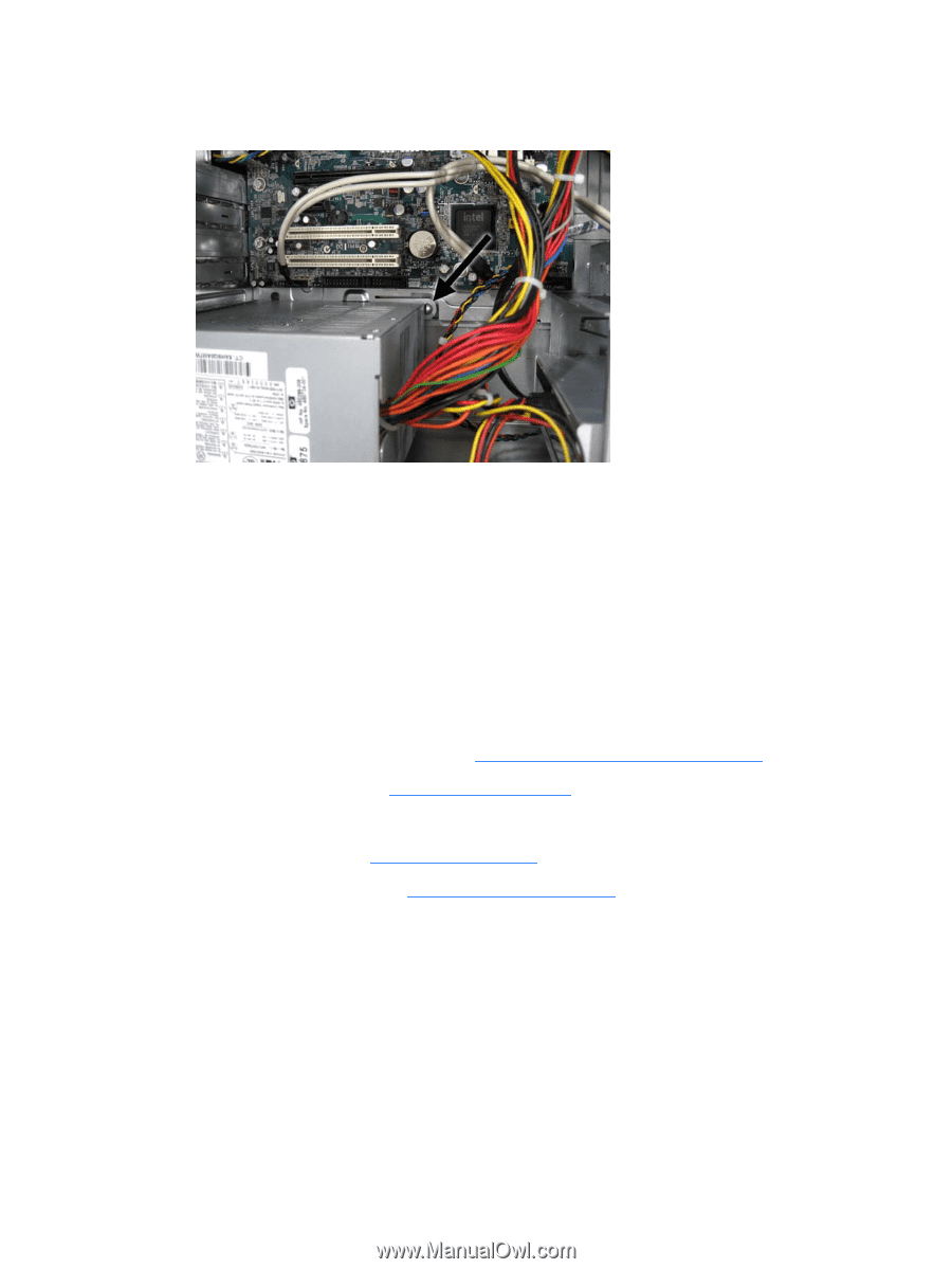
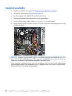
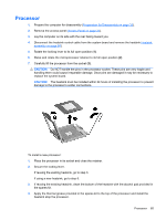
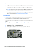
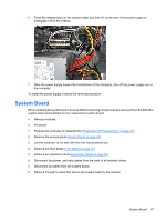
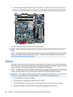
6. Press the release latch on the chassis base, and then lift up the rear of the power supply to disengage it from the chassis. 7. Slide the power supply toward the front/bottom of the computer, then lift the power supply out of the computer. To install the power supply, reverse the removal procedure. System Board When replacing the system board, be sure that the following components are removed from the defective system board and installed on the replacement system board: ● Memory modules ● Processor 1. Prepare the computer for disassembly (Preparation for Disassembly on page 32). 2. Remove the access panel (Access Panel on page 33). 3. Lay the computer on its side with the rear facing toward you. 4. Remove the front bezel (Front Bezel on page 34). 5. Remove an expansion cards (Expansion Cards on page 40). 6. Disconnect the power, and data cables from the back of all installed drives. 7. Disconnect all cables from the system board. 8. Remove the eight screws that secure the system board to the chassis. System Board 67
-
 1
1 -
2
-
3
-
4
-
5
-
6
-
7
-
8
-
9
-
10
-
11
-
12
-
13
-
14
-
15
-
16
-
17
-
18
-
19
-
20
-
21
-
22
-
23
-
24
-
25
-
26
-
27
-
28
-
29
-
30
-
31
-
32
-
33
-
34
-
35
-
36
-
37
-
38
-
39
-
40
-
41
-
42
-
43
-
44
-
45
-
46
-
47
-
48
-
49
-
50
-
51
-
52
-
53
-
54
-
55
-
56
-
57
-
58
-
59
-
60
-
61
-
62
-
63
-
64
-
65
-
66
-
67
-
68
-
69
-
 70
70 -
 71
71 -
 72
72 -
 73
73 -
 74
74 -
 75
75 -
 76
76 -
 77
77 -
 78
78 -
 79
79 -
 80
80 -
81
-
82
-
83
-
84
-
85
-
86
-
87
-
88
-
89
-
90
-
91
-
92
-
93
-
94
-
95
-
96
-
97
-
98
-
99
-
100
-
101
-
102
-
103
-
104
-
105
 |
 |